#jlcpcb
Text


Flexible circuit boards manufacturing (JLCPCB, 2023)
Inkjet print head uses a fiducial camera for registering an FPC panel, and after alignment it prints graphics with UV-cureable epoxy in two passes
#jlcpcb#pcb#fpc#manufacturing#manufacture#factory#electronics#fiducial camera#camera#cv#opencv#computer vision
114 notes
·
View notes
Text
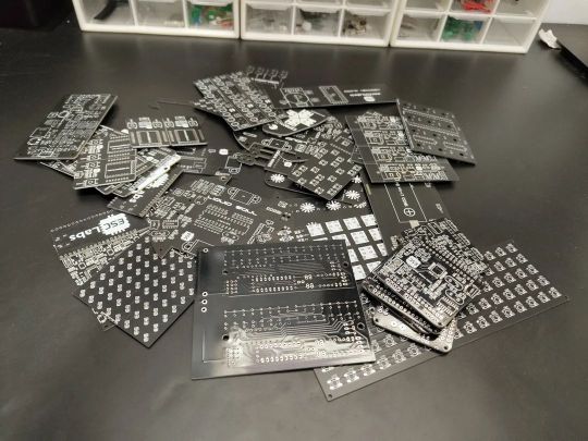
A little preview of something I've been working on the past couple weeks:


A lot of firsts in this project — my first time using assembly service, the largest PCB I've ever ordered, the longest BOM, the most complex schematic ... Basically, it is the culmination of many years of work all brought together.
But speaking of firsts ...

My goal is to have this project at least partially functional and ready to show off at VCF Southwest in June. This will be my first VCF show, and it's the first VCF Southwest show in over a decade. It's shaping up to be a great show and I am excited to be a part of it. I've already reserved my exhibitor table.
30 notes
·
View notes
Photo
Black PCB is 🖤 from @jlcpcb #pcb #pcbdesign #electronics #pcbassembly #makers #easyeda #tinkercad #project #engneering #automation #pcbs #black #jlcpcb https://www.instagram.com/p/Cp2fhgsr7MA/?igshid=NGJjMDIxMWI=
#pcb#pcbdesign#electronics#pcbassembly#makers#easyeda#tinkercad#project#engneering#automation#pcbs#black#jlcpcb
4 notes
·
View notes
Text
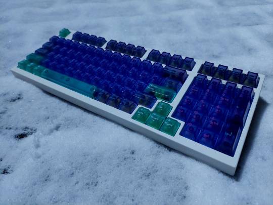
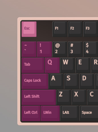
Leopold FC980m
Custom PCB (source)
Aflion Melody and Runner switches
Deadline Studio AirR PC keycaps
Lightblue painted stock aluminium plate
Stock plate-mounted clip-in stabilizers
More under the cut.

This build took well over a year to actually get it to it's current state and it's technically not done yet, considering I still have to tune and lube the stock stabilizers.
Issue number 1 before everything else was getting the cherry mx brown switches out of the old PCB to be able to remove the plate because I didn't want to order a custom plate or go plateless. The solder used on the original PCB has a stupid melting point so not only did I have to dilute the solder with my own that melts at roughly 320°c, but my soldering iron was set to 410°c (or more for specific spots, more on that later). A good chunk of the extracted switches were simply not usable anymore afterwards from being slightly molten. The plate has a few hooks and the PCB has holes for them to hook into, one of which is a PTH (plated through hole) hole that goes to the PCB's ground and the corresponding hook lacks paint and is soldered into this hole. This cursed and damned hook was the reason for a lot of frustration as it took quite literally half an hour (maybe more) to de-solder at 435°c while constantly adding and removing solder to slowly chip away at this literal mountain of solder they used.
My next problem was simply getting the new PCB(s). Back then I was a bit tight on money from expenses out of my other hobbies and various mundane things I needed, so it took a month or two to be able to finally order them. Except JLCPCB, the service that was recommended for this PCB by this keebtalk thread, ran out of the MCUs I needed, so I researched if they had any alternatives, but by the time I read enough of the documentation of various alternatives and found one, that one ended up being out of stock as well. So another couple of months passed basically just waiting.
After ordering, an engineer of JLCPCB contacted me because some of the NPTH (non-plated through hole) holes were too close to each other and would be at risk of breaking while drilling and the best option seemed to be just making them PTH holes, because the hook holes aren't connected to anything and the plate's paint makes it non-conductive anyways so it should be fine. Right?
FORESHADOWING IS A LITERARY DEVI-
I eventually get the new PCBs and of course immediately scratch one of the 5 I ordered (it still works), tested 2 of them and went to work.
Across a couple months (I was preoccupied, blah blah lazy excuses) I slowly chipped away at soldering in the MillMax sockets.
Couldn't have 4 minutes without problems though, now can we?
Trying to install the switches and PCB didn't work because the MillMax sockets add roughly a millimeter of distance between PCB and plate and you can already guess that this doesn't play nice with the plate's hooks. I trimmed off the hooks but left them as little poles for aligning the PCB and so everything would be alright. Right?

I assemble the keyboard fully and plug it in to see... it not working.
I assumed due to the extra millimeter from the hotswap sockets messing with the tolerances, there may be a short to the daughter board, so I took it apart again and taped any contacts and it still didn't work after reassembly. Now I was getting quite annoyed so I took off the top of the casing and tested it like that and surprisingly it worked. Kinda.
As soon as I snapped the top of the case back on, or pressed down on the plate in the bottom left corner, the keyboard would fire A bunch of keys at the same time.
Seeing this set of keys led me to the right path. I double checked this side of the PCB and saw that the hole for the PCB hook next to caps was PTH rather than NPTH and connected to one of the contacts for caps. Remember when I said one of the hooks was connected straight to ground? Or how I had to remove part of the plate hooks, thus removing the paint that prevents it from conducting electricity? Yeah. One strip of tape later and everything is fixed and works perfectly fine.
That's basically it. It was a pain, but it looks, sounds and types nicely.
I'm happy with how it turned out.
2 notes
·
View notes
Text
(hehe smart knob)
But in all seriousness this looks p cool. It'd be a fun project to make a fancy schmancy stim toy at least xD
2 notes
·
View notes
Text
I had begun laying out a PCB drone frame for the esp32 drone project and I was telling the University Friends about it when we checked the local hardware store and saw that this one premade PCB flight frame was in stock, so I've just bought that instead.

Designing one from scratch could be fun, but this way I can get into control logic faster and with a reliable and not horribly cobbled together platform. The board design is open source so if you want you could probably get most of it run off by JLCPCB. As best as I can tell no one has actually built a quadcopter on this platform before so hopefully that's just because no one has tried.
This is basically exactly what I was laying out anyway, just with more SMT parts. MOSFETs driving the motor pads with flyback diodes, an MPU6050 inertial measurement unit, and a basic battery management system. It also costs way less for me to just buy this, all I need now is to print some motor mounts and track down some 720 coreless motors. In the meantime l can try and bring this up and get the underlying control philosophy worked out.
I could run Ardupilot and I may well use it at some point but a) it's still very experimental on ESP32 and b) I really enjoy controls design.
15 notes
·
View notes
Text

just got version two of my modular wearable SAO badge system. version one is on the left, version two is on the right. SAO mount module on top, power module on bottom. coin cell and AA battery for scale; these are really small!
major iterations include:
most importantly: larger holes in the corners, because the version 1 holes are so small, you can't find common screws to fit them
added a physical power switch spot on the power module, compatible with common little EG1218 switches
moving the JLCPCB serial number to the back
slightly moving around the labels otherwise
looks like i have some soldering to do tonight...
14 notes
·
View notes
Text
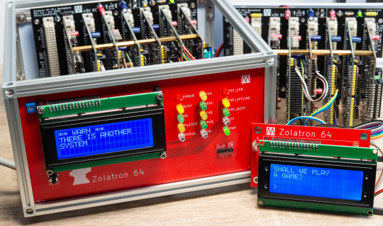
What's better than a 6502 homebrew computer?
What's better than a #6502 #homebrew computer?
Yep, you guessed it – two of them.
One of the side effects of ordering PCBs from the likes of JLCPCB is that you have to order at least five copies of each board.
This doesn’t quite mean that I have enough PCBs to make five Zolatron 64s. For one thing, each of the machines above uses two of the 65C22 VIA boards (one for controlling the LCD and some LEDs, the other as a user port and user timer).…
View On WordPress
16 notes
·
View notes
Text
りくらぼが初めて入社した会社のお話 #猫ミーム
JLCPCBの3Dプリントサービスは$0.3から!! https://ift.tt/kvJwzNh □Twitterはこちら https://twitter.com/riklabo #りくらぼ ...
via YouTube https://www.youtube.com/watch?v=rtj1aZLZ_Ns
0 notes
Text
just placed an order with jlcpcb for my first every custom-make circuitboard
fingers crossed I didn't screw anything up, because that's over 150 components I'll be soldering to it
1 note
·
View note
Text
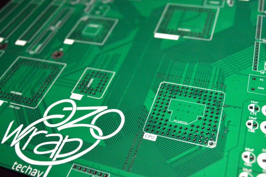
Introducing Wrap030-ATX
New Boards Day!

They're here!
This is a project that has been a long time coming, and something I have wanted to do for a long time.
This is the largest, most complex PCB I have ever designed — a 9.6x9.6 inch (244x244mm) square, 4-layer, complete motherboard for my MC68030 homebrew computer project.
It is designed to support the Motorola MC68030 CPU, MC68882 FPU, two 72-pin SIMM sockets, 512kB ROM, two serial ports, one parallel port, PS/2 keyboard, 4-bpp VGA video, IDE hard drive, and three ISA expansion slots. A complete system all in a microATX form factor.
This builds on my previous work with the 68030, based heavily on my wire-wrap project and the boards that followed. It's a project over four years in the making. I have made a few improvements on the old design, like 16550-compatible serial ports and an updated memory map to support much more RAM in a contiguous space.
Keeping with my existing system designs, I've combined most of the logic into a set of CPLDs. This makes things like PCB layout and logic debugging so much easier. Most of the remaining discrete logic on the board is 74'245 bus transceivers for driving memory and the ISA slots.
I've kept the name "wrap030" in honor of the project's origin as a wire-wrapped prototype, despite the move to proper PCBs. It's just what I've been calling the project in my own head (and design files) all this time, so at this point no other name would feel right.
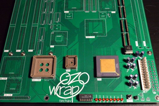
I of course wasted no time starting to assemble one, but I did stop myself from getting too carried away with the soldering iron. I want to be methodical and test each section before moving on to the next.
I have already found one major error in my board layout — the footprint for the VGA connector is backwards. I may need to bodge together some kind of adapter.
So far I've confirmed the minimalist AT power supply section works with no major shorts on power supply rails, and the reset circuit is working as expected. Next step is to try a free run test with the CPU to ensure the system clock and CPU are working. Once that is confirmed working, I can start loading logic for accessing ROM. My goal is to have it at least running BASIC on a serial terminal by VCFSW in June.
I've forked my existing wrap030 repository on GitHub for this new Wrap030-ATX, since it does make some breaking changes that will require updates to logic and programs. New repo is here:
#homebrew computing#mc68030#motorola#motorola 68k#motorola 68030#vintage computing#jlcpcb#vcf southwest#wrap030-atx
32 notes
·
View notes
Photo

Advanced Arduino Uno with type C USB and built in Neopixel LED #arduino #microcontroller #programming #embedded #electronics #electronics #tech #arduinouno #pcb #circuit #neopixel #led #lights #jlcpcb @arduino @jlcpcb https://www.instagram.com/p/Cm_uaEoPmNL/?igshid=NGJjMDIxMWI=
#arduino#microcontroller#programming#embedded#electronics#tech#arduinouno#pcb#circuit#neopixel#led#lights#jlcpcb
3 notes
·
View notes
Text
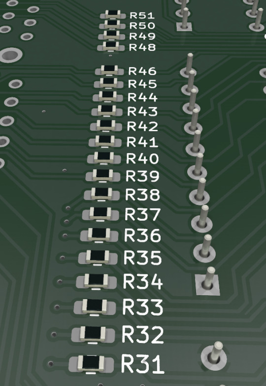
I have this old Leopold FC980m, which is an 1800 layout board, that's been sitting here de-soldered and taken apart for quite some time now.
The plan was (and is) to replace the PCB with a custom one that I can flash QMK/Via onto by following the process in this Keebtalk thread, as well as Millmaxing the new PCB and changing the switches because stock Cherry Browns just aren't that great once you get used to better objectively better switches.
Unfortunately JLCPCB has not had either of the fitting MCUs in stock for quite a long time now, or rather every time I check they're not in stock. This means I've had this project sitting here taken apart collecting dust for nearly a year at this point.
2 notes
·
View notes
Text
Без ПК и принтера: Как изготовить плату по технологиям СССР
Вы когда-нибудь задумывались, как в советское время радиолюбители без помощи сервисов «JLCPCB», лазерно-утюжных технологий и вспомогательных программ изготавливали печатные платы? Процесс любопытный и увлекательный, поэтому предлагаю повторить то, что делали наши отцы и деды.

https://sdelaysam-svoimirukami.ru/9219-bez-pk-i-printera-kak-izgotovit-platu-po-tehnologijam-sssr.html
0 notes
Last Seen Blogs

lmnlad
lad

sgnorp
pensieri e parole

mykekarter
Music Producer
sgb-ag
SGB Sicherheitsgruppe
Berlin AG

nunc-est-tumbilirendum
Nunc est tumbilirendum