#icestudios
Text


renell medrano (renellaice)
#renellaice#beautiful#beach#renell#medrano#ice#icestudios#new york#black film photographer#vogue beauty
12 notes
·
View notes
Text
Antha Panthaa for Ice Studios, directed by Renell Medrano
#antha panthaa#ppantthaa#renell medrano#ice studios#icestudio#ice studios co#ice studios shop#icestudios.co#renellaice
8 notes
·
View notes
Photo

R E N E L L A I C E X T H A N K S N A P G O D Pants: @boohoomanofficial Shirt: @renellaice @thankyousnapgod Model: @chrishnadagod #ChrishnaDaGod #ChrishnaPhotography #ChrishnaPhotos #ThankyouSnapGod #Renellaice #Icestudio #Harlem #Fashion #BoohooMenOfficial #NewYorkPhotographer #NewJerseyPhotographer #LosAngelesPhotographer #DallasPhotographer #HoustonPhotographer #AtlantaPhotographer #PhillyPhotographer https://www.instagram.com/p/Co5hXQlJqEw/?igshid=NGJjMDIxMWI=
#chrishnadagod#chrishnaphotography#chrishnaphotos#thankyousnapgod#renellaice#icestudio#harlem#fashion#boohoomenofficial#newyorkphotographer#newjerseyphotographer#losangelesphotographer#dallasphotographer#houstonphotographer#atlantaphotographer#phillyphotographer
0 notes
Note
His mother doesn't like her, she's very sane, check out that counterfeit song - close to your chest. She's too polite to say it she's not falling in her lies. Sam likes those random pictures of people not for her. Narcissists know how to win over everyone, they know how to be "good" it's a manipulative thatic. Maybe his family feels they aren't being kind enough to support Jamie in the wrong choices and made that New Year's sacrifice. They may have had fun snowboarding but in that pic of just Jess and his parents, all distant, his parents didn't seem to appreciate it so much like in the pic just Jamie and parents.
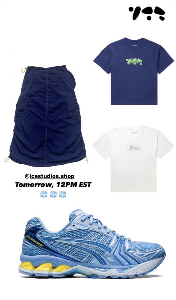
The tour on mtbarchelor is all in the script it's pre-launch of portfolio in which you've had screenshots some products from the webpage icestudios everything blue(😂), it represents an "ice" brand, snowboarding has everything to do with it.
Funny, in the comments on her post someone asked where she was, she didn't want tell localization. Later all should know Jamie isn't private. 😂
Jamie went back to MtBarchelor and just linked their instagram page, it could be those responsible knew he was there and contacted him to come back and take those pics, he supports the "snowboarding". Influencers get paid for this, it couldn't have been any different, on the instagram page they have photographers. It didn't seem like made for her the latest Jamie pictures. The shadow in the picture is distorted, the person is wearing a white long sleeves shirt under coats, when she would be wearing bitch clothes under the coat. It seems it's a male.
Or, she had been so manipulative to the point wearing long sleeves under the coat. As you said before she must take hundreds of pictures to get the perfect one. She may have realized that New Years Eve was a shame, no engagement, lost followers and made him come back just to try more pictures again.😂
First, i suspected he was with Joseph because there is a suspicion that he would return to the series, it would be a spoiler if anyone saw the two of them together or anyone of the series. He has friends, last year he posted a story where he went to a concert with a male friend and this woman didn't go together when he was recording new songs in the studios.
I don't have much to add to this (because I agree with all of it) other than the "colourized photos" that appear to show someone wearing all white. Jess's snowboarding outfit is all black. Except maybe the two times she wore the Ice coat but she still wore dark pants. Unless she bought some entirely new snow gear just to take photos with Jamie and not post them it doesn't track that she was with him when he went on that trip. Also, since he appears to be having such a good time she'd certainly want to prove she was there at all costs to show that he could have a good time with her. The lack of any interaction from any of Jamie's family on her post about the trip before that says more than words need to say.
7 notes
·
View notes
Text
Also want to touch on one of the blogs saying that I'm lying and exaggerating Jamie and Jess's relationship timeline of being "several years". One of them tried to say that it was only confirmed in 2022 that they were dating, so it's been barely 2 years. But they've been together since AT LEAST mid-2021, but honestly probably for some time before that. They went on a road trip across Route 66. And idk about you, but I probably wouldn't embark on a cross-country road trip with someone I wasn't even dating or had only been dating for a couple months. Jamie also had pics of this on his Instagram before archiving most of his feed.


Edit: some of Jamie’s photos and his caption, featuring motion blurred Jess and even an #icestudios lol
3 notes
·
View notes
Text
Icestudio: Drag and Drop FPGA programming and learning
https://github.com/FPGAwars/icestudio
Comments
0 notes
Photo

時間已悄悄邁入新的一年❷⓿❷⓿! - 收到這組照片心裡滿是暖暖的感謝,感謝我們辛勞的宏吉員工細心製作檢查,每一份都是那麼的珍貴! 特別感謝 Ice Studio 雪人音樂 @peggyhsumusic ❄️美麗的冰樂精靈許哲珮 Peggy Hsu第九張創作專輯《失物之城》— Candle Box Printing & Packaging工作美照分享給你們希望是最美麗的祝福🥰🥰🥰 ㊗️所有人有下個奇幻的十年🌟 #來自巫女的火焰祝福 #可私藏與分享的秘密 #IceStudio雪人音樂 #許哲珮PeggyHsu #冰樂精靈 #搶購一空 #哪位幸運粉絲搶到了呢 #太美不敢看 https://www.instagram.com/p/B6vloUFFkxa/?igshid=1bol8ozaks8k8
0 notes
Text
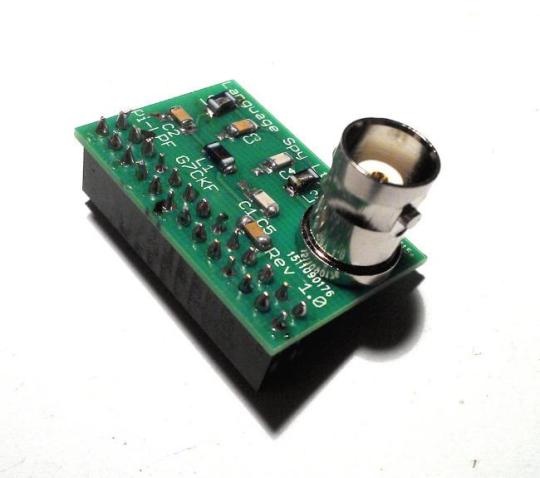
“Hello World” in morse: turning an FPGA into a radio transmitter
I’ll try here to explain everything that is going on in this picture, but first, the origin story. I recently tweeted this photograph of my first ever FPGA project:

Actually this is from a slightly different angle. Bonus! I got more attention on twitter from this than I’d ever gotten before, with lots of notifications on my phone throughout the next days, and of course I’m super flattered. So when a few people request a better explanation I can’t say no!
Even though the people who responded to this are probably a highly technical audience, I’ll try to start very basic and include a lot of links, for the benefit(?) of my other acquaintances whom I’ll pester to read this - so feel free to skim ahead if you’d like.
What is an FPGA?
First, what is this FPGA thing? You can see one in my photo, in front of my keyboard, connected to my computer by a white USB cable. Although this one is small, it contains a lot of the basic components from which digital circuits (like a CPU) are built: logic gates which can compute things, and flip-flops and RAM which can store stuff.
But unlike a CPU, the components in an FPGA are reconfigurable: you get to decide how they are connected together. And you can do it without having to solder millions of tiny wires and losing tiny transistors between the keys in your keyboard. Just describe how you’d like the circuit to be connected on your PC, using a “drag-and-drop and draw wires” program or a text-based “hardware description language”, and through the magic of logic synthesis you can make your circuit come alive within the FPGA.
The trick to it is that all the components in the FPGA are already all connected together in lots of ways, and your computer is just telling the FPGA which of these connections should be on or off - like a light switch decides if your lamp should be connected to power or not.
There are also connections from inside the FPGA to the outside of the board, where you can connect external components like an LED, an LCD display or a keyboard to your circuit.
The specific FPGA I’m using is the TinyFPGA BX. It’s small, very cheap at $38, and is fully open source hardware. All the software you need is open source too, so it’s all free and easy to get access to, and the TinyFPGA page has lots of great links to everything you need to get started.
How did I turn it into a radio transmitter?
Here comes the plot twist: it was a radio transmitter all along.
In order to keep the digital logic of the FPGA in sync and working in unison, it is equipped with an oscillator which transmits a clock signal - a signal that switches between high and low at regular intervals. You’ve probably heard about “clock rates” before, because it is one of the things that decides the performance of a computer, and these days it is usually measured in GHz.
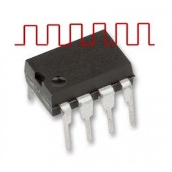
Now simply by directing the FPGA to route the signal from this clock source out to one of it’s external connections, and connecting it to a small piece of wire, we have a radio transmitter! See the screenshot of this setup in the Icestudio FPGA programming environment, possibly the simplest example imaginable:

The output, and the wire connected to it, will be driven to high and low voltage levels by the clock signal, and waves of electromagnetism will spread out across the universe. Imagine the piece of wire (or “antenna”) as a tiny oar splashing up and down in the fabric of space time, in rythm with the clock signal.

But there are some serious disadvantages to the radio signal we are generating here. First, the “oar” of the antenna is very small, and the “muscle” of the clock signal is not very strong, so it’s can’t make very big waves - the transmission is not very powerful. But that is probably for the best, because trying to transmit using a square wave like the 16MHz clock signal will, in addition to a signal on 16MHz, create a lot of “harmonics” - unwanted signals on other frequencies.
Because I’m an amateur radio enthusiast, I have a very nice radio receiver sitting on my desk that can receive and display the transmitted signal in a very nice way (specifically a LimeSDR, It’s visible on the right in my first picture). Here’s a screenshot from GQRX, the program I’m using to control it:

It’s tuned to 16 MHz (the red vertical line), but you can also see some more of the radio spectrum on each side of it. In addition to the sharp peak of the main signal on 16MHz, there is a very apparent cloud of noise surrounding it - which we can see here as a raised area on the "panadapter” up top, or a brighter, yellow color around the 16MHz line on the “waterfall” below. There are also weaker, but still very visible symmetrical peaks to the left and right of the main signal.
Outside of what we can see in this screenshot, there’s also strong “harmonics” being transmitted on other frequencies, like 8 or 24 MHz. In short, what we’re doing here is generating what’s usually called EMI - ElectroMagnetic Interference, and it’s a Bad Thing™. This is the reason real products need conductive shielding, and try to keep wires as short as possible to keep them from acting as antennas. And of course, you should never connect a signal like this to an amplifier - because you don’t want to end up disturbing someone’s pacemaker or interrupting emergency communications.
(Just to make sure noone gets the wrong idea, the TinyFPGA BX itself seems well shielded and I’m hardly able to detect it being on without attaching the “antenna”.)
What you’d want, and what “real” radio transmitters generate, is something closer to a nice smooth sine wave like this:
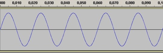
Now it’s quite possible to get from a square wave to this, by passing the signal through a “filter” which can be easily constructed from inductors and capacitators. Well, if you consider soldering tiny components easy ...
I was able to assemble a kit for such a filter, allowing me to transmit “real” radio signals from the output pins of a Raspberry Pi with no additional components, and be received across town several kilometers away! And although that was with a much better antenna, it was without any amplification. So again, a warning about being very careful about what you transmit, intentionally or unintentionally, because even very weak signals can be heard quite far away.
Now there’s a couple of more things that are Bad™ about the 16MHz square wave signal we generated earlier: First, it’s not a frequency on which I am legally allowed to transmit(!). The radio spectrum is quite heavily regulated, but there are some frequency ranges for “free” use. These are typically quite crowded. There is one area around 433 MHz that is used heavily by all sorts of gadgets like wireless temperature monitors or doorbells, and another around 2.4GHz which is very heavily used by Wi-Fi, Bluetooth and other high-bandwidth devices.
The other problem with our original signal is that it is very boring - just a steady buzz at 16MHz, hardly worth transmitting or listening to.
As a licensed (though inexperienced) amateur radio operator (my callsign in LB7HH!), I also have permission to transmit on amateur radio bands, with certain requirements. One of them is that during any transmission, I have to regularly include my call sign.
So with some copy-pasting and slight tweaks, here’s my first FPGA project:
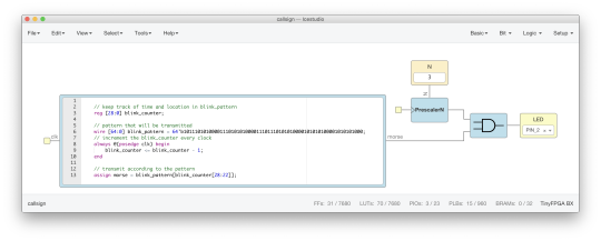
The large rectangle on the left is a block of Verilog hardware description code - it’s a slight modification of the code from the TinyFPGA-BX project template. The code in the template blinks the LED in a SOS morse pattern. By doubling the size of the string, I was just exactly able to fit my callsign in morse code instead!
To the right, I first use the builtin “PrescalerN” component which can reduce the clock frequency by dividing it with 2^N. Lucky for me, there is a value of N that results in a frequency I’m legally allowed to transmit on - 2MHz, which is exactly the upper edge of the 160M band.
The last component is an AND gate which combines the two signals, only letting the 2MHz frequency signal through when the morse signal is high. And then it’s connected out to PIN_2 and my “antenna”. And that’s all there is to it.
So how powerful is this transmitter? I haven’t done the math, but judging by what similar hacks can do it should be around milliWatt at most, and with a very poor antenna the effective radiated power is much lower still. Which is actually a good thing, as I didn’t build that filter for 2MHz yet.
And I probably won’t, because the project I got this FPGA for is actually very different - implementing my own CPU design. I’ll just have to learn a lot more Verilog first ...

2 notes
·
View notes
Text

Renell Medrano, Ebony Riley, Najeen Michelle
9 notes
·
View notes


Photo

Bet on yourself and watch you win everytime. Shirt: @renellaice @thankyousnapgod Model: @chrishnadagod #ChrishnaDaGod #ChrishnaPhotography #ChrishnaPhotos #ThankyouSnapGod #Renellaice #Icestudio #NewYorkPhotographer #NewJerseyPhotographer #LosAngelesPhotographer #DallasPhotographer #HoustonPhotographer #AtlantaPhotographer #PhillyPhotographer https://www.instagram.com/p/Co4o81mOxIy/?igshid=NGJjMDIxMWI=
#chrishnadagod#chrishnaphotography#chrishnaphotos#thankyousnapgod#renellaice#icestudio#newyorkphotographer#newjerseyphotographer#losangelesphotographer#dallasphotographer#houstonphotographer#atlantaphotographer#phillyphotographer
0 notes
Note
"Like…what is the end game for anyone in this circle and how does anyone benefit from allowing Jess to pretend to be in it?"-The whole thing appears to be some sort of scheme on her end. Jess may be promising things to these people using Jamie. Who knows if she took money from them. What has she been telling Jamie? What if he didn't know until recently. There are people out there that are really great scammers. Jess seems like one of them. Nothing about her appears to be honest.
She could be promising things based on her connection to Jamie. It would explain a lot. As I mentioned before the first use of her #IceStudios was in 2021 when she was already with Jamie. She may have convinced Renell (who she clearly already knew via her connections from Donna Management where she met Justine Skye) that she could help "boost" her studio/products by being allowed to hashtag everything to it. However, I've noticed that Renell has similar practices. Renell also posted the Tommy Hilfiger campaign and tagged Ice Studios and I still cannot find any connection between the two. Tommy Hilfiger does not follow Renell or Ice Studios. Is this something that Jess told her to do? Was it both of their ideas? Did Jess only really get this "business deal" with Renell because of Jamie? It seems like there's a whole layer of scamming here somehow and it always comes back to Jess.
Since all of this is done so covertly in such odd ways that no one would really ever notice or question unless they were trying to, it's very likely she did somehow hide it from Jamie (or manipulate him into thinking otherwise). It does look like it's slowly dawning on him that she's not what she once said she was and he seems to be distancing himself from her. As you may have noticed there was no confirmation from his end that the beach video she posted was from that day or anywhere near current. I think she's desperate to keep up this image and idea that she and Jamie are still together when really they are probably on the rocks. I wonder what kind of tantrum she's going to have when it all ends for her and she goes back to being a nobody.
3 notes
·
View notes
Last Seen Blogs

the-uthought
U-Thought

collectate
goal of the century

kuroshirosb
DS Pkmn Enjoyer

tach-seo
الحائط التقني

prettyboyfucks
jay