#Matrix LED
Text
Yenilenen Ford Fiesta Türkiye’de
B segmentinin önde gelen modellerinden Yeni Ford Fiesta, üç donanım seviyesi ile satışa çıktı. Giriş donanım olarak konumlanan Style, üst donanım olarak konumlanan T (more…)

View On WordPress
#EcoBlue#ecoboost#Fiesta#Ford#Ford Co-Pilot#Ford Co-Pilot360#Ford Fiesta#Ford Türkiye#FordTR#Hybrid#Matrix LED#Otosan#Powershift#ST-Line#Titanium
1 note
·
View note
Text
Earthspark Spoilers ahead
So, this is ES Orion Pax pre-matrix:

that dont look like an archivist, cop, or even a dockworker to me! Dockworker maybe, but surely they'd show him doing something more recognizable as that, like moving boxes or something?
He's definitely not a clerk or other whitecollar worker, which yay, i missed good ol blue collar laborer orion pax.
But i think its interesting, that he even looks a bit like he's mining.
#transformers#transformers earthspark#earthspark spoilers#orion pax#optimus prime#a quick check of tfwiki says Orion and Megatron were friends who co-led the revolution? in some guidebook i dont have#earthspark give me pre-matrix orion pax backstory pleeeeease
298 notes
·
View notes
Text
Here’s a relatively comprehensive list of my interests separated into categories based on how well I think I know them:
God itself does not know this like I do:
BATIM
Vita Carnis
TMA
The Darkside Detective
My knowledge is extensive, yet incomplete:
Gemini Home Entertainment
Paper Mario (JUST THE FIRST ONE)
Led Zeppelin (I had a phase in middle school)
BATDS
Kirby (would be higher but I haven’t fully caught up on lore since Star Allies)
The scythe book series
TMAGP
I am no expert, but I am no fool either:
FNAF (I used to consider myself an expert in FNAF lore. I have since been humbled)
Whale sharks (just the animal)
BATDR
The Matrix
Star Trek
Monument Mythos
Liminal Land
Harmony and Horror
Angelology
Human anatomy (bones, organs, muscles, ect)
Pokémon
Lethal company
The Bible (I am not religious)
My knowledge is rather limited in the grand scheme of things:
Bugs
The Walten Files
Colour theory
Mincraft (I know a lot, but only up to the water update where they added dolphins and stuff)
BATIM but specifically the books
Animated Barbie movies
Demonology
Space
My knowledge is but a drop in the ocean of information:
Elden Ring (and Bloodborne and all the souls games really. I would like to know more about them though)
Dinosaurs
The meanings flowers have
Psychology
Ghosts
Junji ito books (I am not in the financial position to purchase any)
I don’t know shit (but I want to):
Greylock
The last of us
Bauldurs gate
#batim#analog horror#the darkside detective#vita carnis#tma#tmagp#batdr#gemini home entertainment#paper mario#led zeppelin#batds#kirby#scythe#fnaf#whale sharks#the matrix#star trek#monument mythos#liminal land#harmony and horror#angelology#human anatomy#pokémon#lethal company#bugs#twf fanart#the walten files#colour theory#minecraft#ghosts
16 notes
·
View notes
Text

#fujifilm#fujifilm xt20#photography#urban photography#infrastructure#road infrastructure#road signs#highway#variable message sign#matrix sign#led matrix
2 notes
·
View notes
Text
i am trying to do so much rn it's truly fucking bonkers like it's all really good stuff that will measurably improve my life! but my god. every single day so much is happening
#like im preparing to move. while also making a major career change. and additionally getting ready for grad school#and also needing to program this LED matrix in less than two weeks. and ive gotta get a fucking passport. AND
3 notes
·
View notes
Text

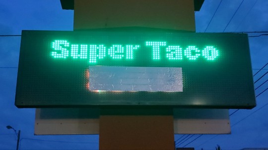

... When I saw an LED sign for super tacos, I again felt the urge to make a gif...
I used fontmeme.com and photomosh.com
#tacos#super taco#gif#animated gif#Mexican Restaurant#taco Tuesday#dine-in#take-out#led sign#dot matrix
3 notes
·
View notes
Text
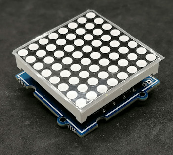
Grove 8x8 LED Matrix am Arduino: Einsteigerfreundliche Programmieranleitung
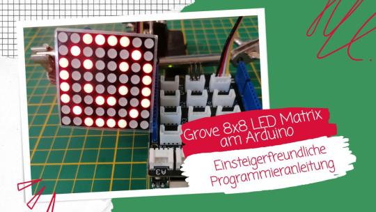
In diesem Beitrag möchte ich dir zeigen, wie du die Grove 8x8 LED Matrix am Arduino UNO R3 programmierst. Der Vorteil von diesem Modul ist es, dass du keine umständliche Verkabelung vornehmen musst, da die Grove Schnittstelle einheitlich ist und ein vorkonfektioniertes Kabel verwendet wird.

Grove 8x8 LED Matrix am Arduino: Einsteigerfreundliche Programmieranleitung
Im Beitrag Arduino Lektion 8: Max7219 8×8 LED Shield habe ich dir bereits ein ähnliches Modul mit dem Chip MAX7219 vorgestellt. Hier soll es nun um eine Matrix mit dem Treiber HT16K33 gehen.

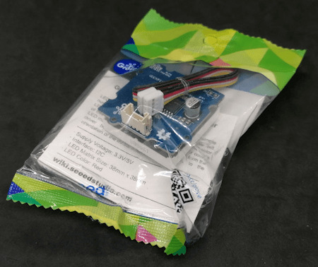
Bezug einer 8x8 LED Matrix mit Grove Schnittstelle
Das mir vorliegende Modul habe ich auf ebay.de für rund 9 € zzgl. Versandkosten erstanden. Du bekommst dieses Modul aber etwas günstiger bei BerryBase für derzeit 8 € zzgl. Versandkosten.
Lieferumfang
Im Lieferumfang der LED Matrix ist neben der Matrix noch ein kleines Grove Kabel für den Anschluss, sowie ein Zettel mit den wichtigsten technischen Daten.

Auf der LED Matrix ist noch eine kleine Schutzfolie, welche du abziehen kannst, ich lasse diese jedoch drauf.
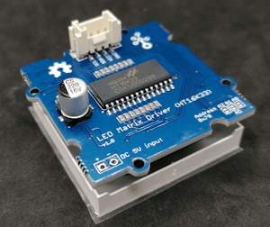
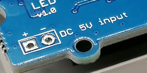
Aufbau der 8x8 LED Matrix
Auf der Rückseite findest du die Grove Schnittstelle, sowie zwei Lötpunkte für die optionale externe Stromversorgung. Des Weiteren kannst du die I2C Adresse 0x70 via 3 Lötbrücken ändern.


I2C Adressen via Lötbrücken
Wenn du die Lötbrücken verbindest, dann kannst du diese Matrix über nachfolgende I2C Adressen ansteuern. Dabei kannst du auch mehrere Muster wählen und so zwischen 8 I2C Adressen auswählen.
Verbundene PinsI2C Adresse-0x70A00x71A10x72A20x72A0 & A10x73A0 & A20x75A1 & A20x76A0, A1 & A20x77
Zur Ermittlung der I2C Adressen habe ich den I2C Scanner von https://playground.arduino.cc/Main/I2cScanner/ verwendet.
Zusätzliche Ressourcen für die Programmierung am Arduino
Damit du diese LED Matrix programmieren kannst, benötigst du entweder
- ein Grove Adapterkabel, oder
- ein Grove Base Shield für den Arduino UNO R3, oder
- ein Seeeduino Nano
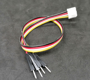
Grove Adapterkabel zu Breadboardpins

Grove Base Shield für den Arduino UNO R3
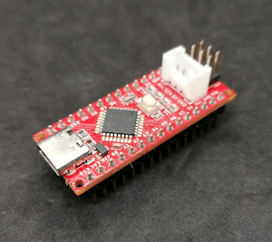
Seeeduino Nano
Das Grove Base Shield hat mehrere Grove Buchsen digital & analog und somit bietet dieses eine sehr große Bandbreite an Möglichkeiten für Projekte. Wenn du lediglich die LED Matrix programmieren möchtest und du hast bereits einen Arduino Nano oder Arduino UNO dann
Programmieren der LED Matrix am Arduino via I2C
Damit die LED Matrix mit HT16K33 Treiber angesteuert werden kann, müssen wir in der Arduino IDE eine zusätzliche Bibliothek installieren. Diese können wir uns als ZIP-Datei vom GitHub Repository Seeed-Studio/Grove_LED_Matrix_Driver_HT16K33 herunterladen.
Weitere Informationen zu diesem Modul findest du auf der englischen Wikiseite von Seeedstudio https://wiki.seeedstudio.com/Grove-LED_Matrix_Driver-HT16K33/.
Anzeigen eines Smileys auf der LED Matrix
Für die Erstellung eines Smileys kannst du den LED Matrix Editor unter https://xantorohara.github.io/led-matrix-editor/ verwenden. Dieser Onlineeditor gibt dir die Möglichkeit, mit der Maus auf der LED Matrix einzelne LEDs zu aktivieren / deaktivieren.
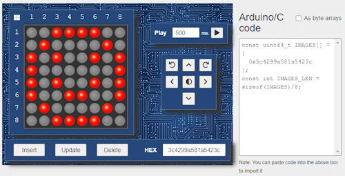
LED Matrix Editor von Xantorohara
Auf der rechten Seite findest du ein Stück Code, welchen du in dein Arduino Programm integrieren kannst. In meinem Fall habe ich ein lachendes Smiley gezeichnet und erhalte den Wert "0x3c4299a581a5423c".
Die Bibliothek liefert zusätzlich ein paar Beispiele, welche mit der default I2C Adresse 0x70 lauffähig sind. Von diesen Beispielen wähle ich zunächst "displaycustom_pictures" und modifiziere dieses etwas.
//Bibliotheken zum kommunizieren mit der LED Matrix
#include
#include "Grove_LED_Matrix_Driver_HT16K33.h"
//Wert für ein lachenden Smiley
const uint64_t smiley = 0x3c4299a581a5423c;
//instanz einer LED Matrix
Matrix_8x8 matrix;
void setup() {
//beginn der I2C kommunikation
Wire.begin();
//beginn der kommunikation mit der LED Matrix
matrix.init();
//setzen der Helligkeit der Matrix
//Werte sind zwischen 0 und 15
//wobei 0 dunkel ist und 15 das hellste
matrix.setBrightness(5);
//In welcher Frequenz die LED Matrix blinken soll,
//Werte sind:
//- BLINK_OFF > kein blinken,
//- BLINK_1HZ > langsames blinken,
//- BLINK_2HZ > schnelles blinken,
matrix.setBlinkRate(BLINK_OFF);
}
void loop() {
//anzeigen eines Bildes
matrix.writeOnePicture(smiley);
//absenden der Daten
matrix.display();
//eine Pause von 10 Sekunden
delay(10000);
}
Auf der Matrix hat man natürlich nur begrenzte Möglichkeiten zur Darstellung von Bildern, jedoch für so kleine Smileys und Pfeile ist dieses bestens geeignet.

lachender Smiley auf der 8x8 LED Matrix
Ausgabe von Scrolltext auf der LED Matrix
Da wie erwähnt die kleine LED Matrix nur begrenzten Platz für Zeichen bietet, gibt es die Möglichkeit Text auf diesem durchscrollen zu lassen.
void loop() {
//Funktion zum anzeigen eines Textes auf der LED Matrix,
//Parameter:
//String - die Zeichenkette welche ausgegeben werden soll,
//Zahl - Wert in Millisekunden pro Zeichen
//Typ
//ACTION_SHIFT - jedes Zeichen einzeln anzeigen,
//ACTION_SCROLLING - den Text durch die Matrix scrollen lassen
matrix.writeString("Hallo Welt!", 1000, ACTION_SCROLLING);
matrix.display();
}
Damit ich das Video aufnehmen konnte, sodass meine Kamera den Text erfasst, habe ich ein kleines Tuch vor die LED Matrix gehängt.
Ändern der default I2C Adresse im Programm
Wenn du bereits Sensoren oder Aktoren am I2C Bus angeschlossen hast, dann kann es vorkommen, dass die default I2C Adresse der LED Matrix bereits belegt ist und du diese im Programm überschreiben musst. (Oder auch, wenn du mehrere solcher Matrixen an einem I2C Bus anschließen möchtest.)
Dazu findest du in der Funktion setup den Aufruf der Funktion "matrix.ini();". Diese Funktion kann einen Parameter vom Typ uint8_t übernehmen und hat als default den Wert des Feldes HT16K33_DEFAULT_I2C_ADDR.
#define HT16K33_DEFAULT_I2C_ADDR 0x70
Wir übergeben also nun den Hexadezimalen Wert, welchen wir aus der Tabelle (siehe I2C Adressen via Lötbrücken) entnehmen können. Und brauchen quasi in unserem Programm nichts weiter anpassen.
matrix.init(0x71);
Vergleich zwischen 8x8 LED Matrix - MAX7219 & HT16K33
Zum Schluss möchte ich dir noch gerne die Unterschiede zur LED Matrix mit dem MAX7219 Chip aufzeigen. Diese LED Matrix verfügt ebenso wie die vorgestellte Matrix über 8x8 LEDs und kann ebenso einfach programmiert werden.
8x8 LED Matrix mit HT16K33 Treiberchip
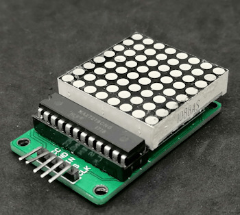
8x8 LED Matrix mit MAX7219 Treiberchip
Jedoch kannst du diese Matrix zu mehreren zusammenstecken und so eine schier endlose Anzeige aufbauen.

MAX7219 Shields auf einem Stativ
Die LED Matrix mit Grove Schnittstelle jedoch kannst du nicht so kaskadierend aufbauen und somit bist du mit dem Modul in deinen Möglichkeiten stärker beschränkt.
Fazit zur Programmierung der 8x8 LED Matrix mit Grove Schnittstelle am Arduino
Die LED Matrix von Seeedstudio mit Grove Schnittstelle und HT16K33 Treiberchip lässt sich super einfach programmieren. Du benötigst wenig Code und über die I2C Schnittstelle und dem Grovekabel hast du deutlich weniger Verkablung als bei der LED Matrix mit MAX7219, leider vermisse ich hier die Möglichkeit die Module kaskadierend zu verbinden und so ein langes Display für Laufschrift aufzubauen.
Mit dem Online LED Matrix Editor kannst du dir jedoch recht einfach kleine Frames für die Matrix erstellen und in den Code kopieren.
Ausblick
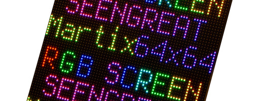
Ich werde nun mal schauen, welche kleinen Projekte man mit dieser Matrix aufbauen kann. Jedoch würde ich eher zu einer RGB Matrix tendieren, denn diese kann bei gleicher Baugröße verschiedenfarbige Pixel anzeigen.
Read the full article
0 notes
Text
https://www.futureelectronics.com/p/semiconductors--Led-lighting-components--led-driver-modules-rev--constant-current-acdc-led-drivers/xi055c180v054bsj1-signify-north-america-1084261
AC/DC led driver circuit, light emitting diode, high-power LED
100 - 277Vac, 55W, 100 - 1800mA, 18-54V, [0-10V], IP66 LED Driver
#Constant Current AC/DC LED Drivers#XI055C180V054BSJ1#Signify North America#ac dc led bulb driver#Module#linear led driver ic#circuit#light emitting diode#high-power LED#LED technology#LED matrix display#LED Driver replacement
1 note
·
View note
Text
Turning Waste Into Gold - Technology Org
New Post has been published on https://thedigitalinsider.com/turning-waste-into-gold-technology-org/
Turning Waste Into Gold - Technology Org
ETH Zurich researchers have recovered the precious metal from electronic waste. Their highly sustainable new method is based on a protein fibril sponge, which the scientists derive from whey, a food industry byproduct.
The gold nugget obtained from computer motherboards in three parts. The largest of these parts is around five millimetres wide. Image credit: ETH Zurich / Alan Kovacevic
Transforming base materials into gold was one of the elusive goals of the alchemists of yore. Now Professor Raffaele Mezzenga from the Department of Health Sciences and Technology at ETH Zurich has accomplished something in that vein. He has not of course transformed another chemical element into gold, as the alchemists sought to do. But he has managed to recover gold from electronic waste using a byproduct of the cheesemaking process.
Electronic waste contains a variety of valuable metals, including copper, cobalt, and even significant amounts of gold. Recovering this gold from disused smartphones and computers is an attractive proposition in view of the rising demand for the precious metal. However, the recovery methods devised to date are energy-intensive and often require the use of highly toxic chemicals. Now, a group led by ETH Professor Mezzenga has come up with a very efficient, cost-effective, and above all far more sustainable method: with a sponge made from a protein matrix, the researchers have successfully extracted gold from electronic waste.
Selective gold adsorption
To manufacture the sponge, Mohammad Peydayesh, a senior scientist in Mezzenga’s Group, and his colleagues denatured whey proteins under acidic conditions and high temperatures, so that they aggregated into protein nanofibrils in a gel. The scientists then dried the gel, creating a sponge out of these protein fibrils.
To recover gold in the laboratory experiment, the team salvaged the electronic motherboards from 20 old computer motherboards and extracted the metal parts. They dissolved these parts in an acid bath so as to ionise the metals.
When they placed the protein fibre sponge in the metal ion solution, the gold ions adhered to the protein fibres. Other metal ions can also adhere to the fibres, but gold ions do so much more efficiently. The researchers demonstrated this in their paper, which they have published in the journal external pageAdvanced Materialscall_made.
How the gold is recovered: Gold ions adhere to a sponge of protein fibrils. Image credit: Peydayesh M et al. Advanced Materials, 2024, adapted
As the next step, the researchers heated the sponge. This reduced the gold ions into flakes, which the scientists subsequently melted down into a gold nugget. In this way, they obtained a nugget of around 450 milligrams out of the 20 computer motherboards. The nugget was 91 percent gold (the remainder being copper), which corresponds to 22 carats.
Economically viable
The new technology is commercially viable, as Mezzenga’s calculations show: procurement costs for the source materials added to the energy costs for the entire process are 50 times lower than the value of the gold that can be recovered.
Next, the researchers want to develop the technology to ready it for the market. Although electronic waste is the most promising starting product from which they want to extract gold, there are other possible sources. These include industrial waste from microchip manufacturing or from gold-plating processes. In addition, the scientists plan to investigate whether they can manufacture the protein fibril sponges out of other protein-rich byproducts or waste products from the food industry.
“The fact I love the most is that we’re using a food industry byproduct to obtain gold from electronic waste,” Mezzenga says. In a very real sense, he observes, the method transforms two waste products into gold. “You can’t get much more sustainable than that!”
Source: ETH Zurich
You can offer your link to a page which is relevant to the topic of this post.
#2024#advanced materials#chemical#chemicals#Chemistry & materials science news#cobalt#computer#computers#course#electronic#electronic waste#energy#ETH Zurich#Featured technology news#Food#gold#Health#Health sciences and technology#how#Ideas#Industry#it#LED#Link#Manufacturing#materials#Matrix#metal#Metals#Method
0 notes
Text
Illuminating the Future: Exploring the Dot Matrix LED Display Technology
Introduction
In the world of digital innovation, LED technology has emerged as a game-changer, revolutionizing the way we visualize information. Among the various LED display solutions, the dot matrix LED display stands out as a versatile and efficient option. This blog delves into the intricacies of dot matrix LED displays, exploring their applications, working principles, and the role they play in our everyday lives.
What is a Dot Matrix LED Display?
A dot matrix LED display, also known as an LED dot matrix display or LED matrix panel, is an array of individual LEDs arranged in a grid pattern. Each LED within the matrix is capable of illuminating independently, allowing the display to generate various patterns, shapes, and characters. These displays are commonly available in monochrome (single-color) or multi-color configurations, providing visual flexibility for a wide range of applications.
Understanding the Working Principle
The operation of a dot matrix LED display is based on the principles of multiplexing. Multiplexing is a technique used to control multiple LEDs with fewer input/output pins. In a typical configuration, the LED matrix is divided into rows and columns. By sequentially turning on specific rows and columns at a rapid rate, different LEDs can be activated to form a desired pattern or text.
For example, to display the letter "A" on a 5x7 dot matrix LED display, the corresponding LEDs in the matrix would be activated according to the pattern for the letter "A," with each row being illuminated one after another in quick succession to give the illusion of a static image.
Applications of Dot Matrix LED Displays
The versatility of dot matrix LED displays makes them ideal for a wide range of applications. Some of the common uses include:
Information Displays: Dot matrix LED displays are commonly used in public places, transportation systems, and sporting events to provide real-time information, such as arrival and departure times, scores, and announcements.
Message Boards: LED dot matrix displays are popular for creating dynamic and eye-catching message boards in retail stores, banks, and other commercial establishments to showcase advertisements and promotional content.
Indoor and Outdoor Signage: Due to their high visibility and ability to display custom graphics and messages, LED dot matrix displays are widely used in indoor and outdoor signage for businesses and public spaces.
Clocks and Timers: LED matrix displays are frequently integrated into digital clocks, countdown timers, and stopwatches, providing a clear and legible time display.
Gaming and Entertainment: LED dot matrix displays are also utilized in gaming consoles and handheld gaming devices to render graphics and textual content.
Advantages of Dot Matrix LED Displays
Energy-Efficient: LED technology is renowned for its energy efficiency, making dot matrix LED displays an eco-friendly choice compared to traditional display technologies.
High Brightness: The individual LEDs in a dot matrix display produce high-intensity illumination, ensuring excellent visibility even in brightly lit environments.
Compact and Lightweight: The compact size and lightweight nature of dot matrix LED displays make them easy to integrate into various devices and structures.
Flexible Content: With the ability to display custom content, dot matrix LED displays allow for dynamic and engaging visual experiences.
Conclusion
The dot matrix LED display has become an indispensable technology in today's digital landscape. Its versatility, energy efficiency, and ability to display custom content make it a popular choice for a diverse range of applications, from public information displays to advertising and gaming. As LED technology continues to advance, we can look forward to even more innovative applications of dot matrix LED displays, shaping a brighter and more visually engaging future for us all.
0 notes
Text
A LED dot matrix display is a grid of tiny LEDs that can be individually controlled to form patterns, text, or images, making it a versatile and visually striking display solution. It is commonly used in electronic devices, advertising displays, and scoreboards.
0 notes
Link
0 notes
Text
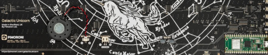
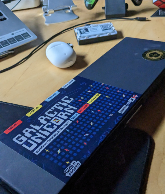
@Pimoroni LED Matrix Galactic Unicorn

Dieses Teil is sooooo coooool! Das Galactic Unicorn LED Panel von Pimoroni mit Raspi Pico W bringt richtig Freude. Ich musste es unbedingt haben. Und jetzt ist es da!
Wenn Du ein Computer Freak bist oder ein Art Computer Nerd, dann kommst Du sowieso nicht daran vorbei. Mit! Und ja, das Teil musste ich unbedingt haben. Aber auch "normalen Leuten" dürften ziemlich viel Spaß machen. Und ja ich hatte wohl lange nicht mehr soviel Spaß an einem derartigen elektronischen Spielzeug. Nicht allein aber gerade weil man es mit Micropython programmieren kann, ist es ein Hit. Jetzt war es wieder lieferbar und ich habe mir gleich eines bestellt! Ob es derzeit noch lieferbar ist? Ja, das dürfte son eine Sache sein. Im Zweifel muss man sich halt mit einer Benachrichtigungs-eMail informieren lassen und dann aber gleich zuschlagen.
Hinweis: Dieser Beitrag enthält unbezahlte und kostenlose Produktwerbung!
Das dieses LED Panel/Display bereits gleich zu Beginn schnell ausverkauft war, zeigt ja schon, dass die Bastelgemeinde es angenommen hatte. Leider war ich gleich zur Markteinführung nicht schnell genug, es war ausverkauft und ich musste mich gedulden. Nicht meine Stärke, was ich gerne zugebe: Jedenfalls vorübergehend war es nicht zu bekommen und dann streikte auch noch die Post in Großbritanien. LOL. Bei diesem Display sind nicht nur 53x11 mehrfarbige LED's verbaut, die sich einzeln ansteuern lassen, sondern auch ein Raspberry Pi Pico W ist direkt auf dem Board angebracht. Das macht es besonders. Es ist für den Pico W optimiert und kann sich durch dessen WLAN Modul bspw. auch mal die Uhrzeit aus dem web holen oder was auch immer. Eine WLAN Verbindung erlaubt uns ja soviel mehr zu realisieren.

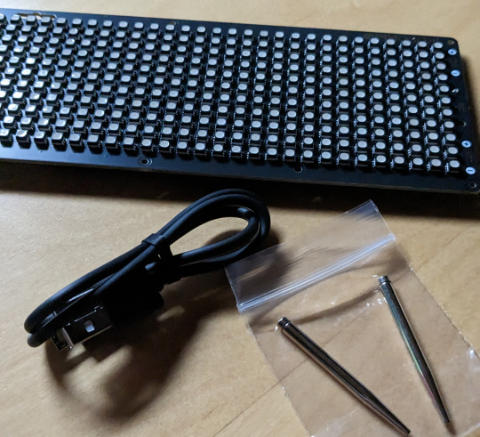
Wie ihr erkennen könnt habe ich mir das Teil unterhalb meines Monitors plaziert. Da Micropython über die main.py Datei direkt loslegt startet das Dispaly automatisch sobald ich meinen Computer eingeschaltet habe. Und ja ich nutze ein Chromebook und damit funzt es auch. Zur Programmierung verwende ich die Linux Version der Thonny IDE. Aber zurück zum Galactic Unicorn. So befindet sich auf dem Galactic Unicorn alles was man in der Regel so benötigt, um direkt loszulegen. Das Display wird für meinen Geschmack in einem sehr hochwertig wirkenden schwarzen bzw. dunkelblauen Karton geliefert und Im Lieferumfang sind neben dem Display selbst zwei kleine Metallstäbe, die sehr nützlich sind um das Display auf dem Tisch aufzustellen. Ein passendes USB.Kabel ist noch dabei und mehr braucht es erstmal nicht.
Nun aufgemerkt Ihr Pixel, RGB und LED Fans. Klar, es gibt andere Lösungen, doch dazu später mehr. Erstmal noch angemerkt, dass ihr alle Spzifikationen natürlich auf der Website von Pimoroni.com findet. Aber um loszulegen, reicht es schon das Display über das USB Kabel mit Strom zu versorgen und der Spaß beginnt, denn es ist bereits alles vorinstalliert.
Hier nur ein paar Dinge, die mir wichtig erscheinen. Erstmal der Raspberry Pi Pico W ist "Aboard", also dabei und vormontiert. Löten musst du also da nicht mehr. Der RP2040 auf dem Pico und Dual Arm Cortex M0+ mit bis zu 133Mhz und 264kB SRAM sind damit gesetzt. Zum Programmieren und Betrieb reicht damit ein USB micro-B Datenkabel. Auch wichtig ist die 2.4GHz Wireless Unterstützung.
Mit 583 RGB LEDs lässt sich bereits einiges anstellen. Diese sind auf einem 53 x 11 Grid angeordenet. Dabei handelt es sich um 3.5mm LEDs und 6mm LED Zwischenraum, was super für tolle optische Effekte ist. Zudem hat das Galactic Unicorn 9 Buttons und einen Reset Button! Auch ein Anschluss für einen Lautsprecher und ein kleiner Lautsprecher ist auch schon verbaut. Ferner verfügt das Board über die Möglichkeit noch einen Akku oder ein Baterrie-Set anzuschließen. Die Nummerieung der 583 LED ist von links nach rechts und oben nach unten angeordnet (y0/x0). Die Helligkeit lässt sich einstellen.
ööö

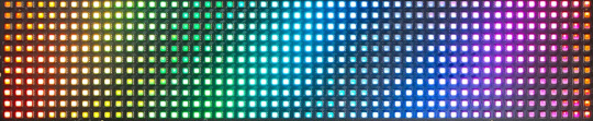
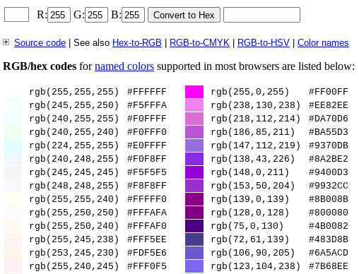
Übrigens zum Thema Farbenwünsche? In den meißten hier verwendeten Scripts werden RGB Codes verwendet. So ziemlich jede Farbe lässt sich damit darstellen. Welche Farbe hat welchen RGB-Code? Dazu schau einfach mal auf diese Website ooder googles es einfach: http://www.javascripter.net/faq/rgbtohex.htm hat auch eine Liste aller Farben mit den entsprechenden Codes, siehe nachfolgendes Bild:
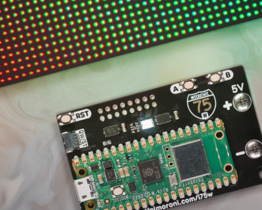
Warum das Galactic Unicorn so genial ist, zeigen uns die Alternativen. Dabei geht es letztlich darum, ob Du dazu beispielsweise einen Raspberry Pi, einen Pi Zero W2 oder einen Pico verwenden möchtest. Und hier kommt es auf die Kosten an, denn ein Pico/Pico W ist da vergleichsweise super günstig. Etwas Vergleichbares wäre das Interstate 75 W von Pimoroni.com (wenn wir den Pico W einsetzen wollen). Das Interstate ist ein RGB LED Matrix Driver, der mit zahlreichen LED Panels funktioniert, welche über die passenden Anschlüsse verfügen. Vorteil ist dann zwar mehr LED und ggf. auch das Zusammenschließen von mehreren LED Matrix Einheiten. Dann wird es aber auch etwas komplizierter.
Das Galactic Unicorn LED Panel ist dagegen "plug and play" und kostet aktuell 47,44 Euro zzgl. Versandkosten. Das Pimoroni Interstate 75 W liegt derzeit bei 18,69 Euro zzgl. Versandkosten und ein LED Matrix Panale mit 64x64, kann man ab ca. 35 Euro bekommen. Die meißten dieser Panels sind aber in der regel etwas teurer. Auch Pimoroni bietet zahlreiche Lösungen dieser Art in unterschiedlichsten Größen an. Letztlich müsst ihr dann schauen wo ihr was und zu welchem Preis bekommen könn und für was ihr es einsetzen möchtet. Zudem kommt noch hinzu, das ich aktuell die Lieferbarkeiten kaum überschauen kann.
Wenn Du Dir gerade das kleine Video anschaust, dann sag mal ehrlich - ist das nicht geil. Sorry, aber ich finde da kaum Worte vor Begeisterung! Auf pimoroni.com findest du übrigens auch Links zu Beispiel-Code, welcher auf GitHub bereitgestellt wurde.
#pimoroni Interstate 75 W#pimoroni Galactic Unicorn LED Panel#Raspberry Pi Pico W LED Matrix#Raspberry Pi Pico W Projekt
0 notes
Text
There's many things that could be upgraded in my Eurorack case, but its biggest actual failing is that out of 16 modules, only four of them have any kind of blinkenlights.
(Those are the two Sigma function generators, the Within the Scope oscilloscope module, and the DSPFX effects box — and of the latter two, the first uses an OLED screen and the second just LED 7-segment displays, so they're kind of borderline.)
#diy#electronic music#homebrew electronics#eurorack#blinkenlights#there are at least colored LEDs on the power supply#but i really need to make up for all the blinkenlessness#the planned tap tempo lfo will have lights#so will the bouncing ball simulator#but i need a big virtual matrix multiplexer or a turing machine#something like the euclidean circles
1 note
·
View note
Photo
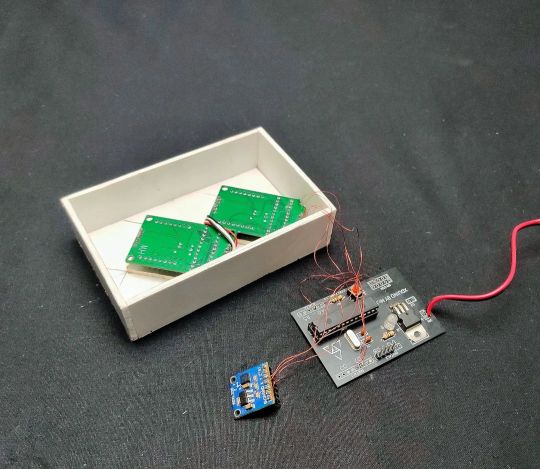
Arduino Hourglass ⌛ using ledmatrix and accelerometer #arduino #ledmatrix #accelerometer #adxl335 #led #ledlight #matrix #electronics #atmega328 https://www.instagram.com/p/CmHKjPHPsjX/?igshid=NGJjMDIxMWI=
1 note
·
View note
Text
Calliope Mini - Würfel programmieren

In diesem Beitrag möchte ich dir zeigen, wie du einen Würfel mit dem Beschleunigungssensor am Calliope Mini programmierst.

Den Mikrocontroller Calliope Mini habe ich dir bereits in einigen Beiträgen auf meinem Blog vorgestellt.
- Vorstellung des Calliope Mini
- Programmieren der RGB LED am Calliope Mini
- Calliope Mini mit DHT11 & LCD-Display
- Calliope Mini mit ESP8285 Modul
Hier soll es nun darum gehen, wie du auf der 5x5 LED Matrix die Augen eines sechsseitigen Würfels anzeigen lassen kannst. Dabei wird mithilfe des internen Beschleunigungssensors das Ermitteln der Zufallszahl gestartet.
Benötigte Ressourcen für dieses kleine Projekt
Wenn du das kleine Projekt aus diesem Beitrag nachbauen möchtest, dann benötigst du lediglich:
- einen Calliope Mini,
- ein Micro-USB Datenkabel
Wenn du ein Batteriepack (im Calliope Mini enthalten) oder Powerbank verwendest, dann kannst du diese kleine Schaltung auch später ohne einen Computer verwenden.

Calliope Mini mit Batteriepack
Microsoft MakeCode für Calliope Mini
Das Onlinetool MakeCode von Microsoft ist eine grafische Programmierumgebung, wo du mit Blöcken deinen Quellcode aufbaust.
Das gute ist, du musst dich nicht anmelden und benötigst auch keinen Account für die Nutzung.
Programmieren in MakeCode
Der Code wird recht lang, aber nicht sehr kompliziert. Ein großer Vorteil von MakeCode (und auch anderen grafischen Programmierumgebungen) ist, dass die Blöcke selbst erklärend sind und untereinander nur in bestimmten Konstellationen zusammen passen.
https://youtu.be/Dkwul8E2oaE
Den fertigen Code als HEX-Datei kannst du dir hier herunterladen. (Dieser lässt sich auch in MakeCode importieren.)
Read the full article
0 notes
Last Seen Blogs

lazurlikeszane
Lazur

pinkcheeks28
Xtina Quinones

aajkitaazakhabar2022
Aaj ki taaza khabar
pinkcheeks28
Xtina Quinones

pinzandneedlez
Duncan