#electromotive devices
Text

90 notes
·
View notes
Text
input
noun
Something put into a system or expended in its operation to achieve output or a result, especially.
Energy, work, or power used to drive a machine.
Current, electromotive force, or power supplied to an electric circuit, network, or device.
Information put into a communications system for transmission or into a computer system for processing.
Any of the items, including materials, equipment, and funds, required for production.
The act of putting in; infusion.
An amount put in.
Contribution of information or a comment or viewpoint.
2 notes
·
View notes
Text
Electromagnetic Induction Class 12 NCERT Notes
Electromagnetic induction is a fundamental principle in physics discovered by Michael Faraday in the early 19th century. It describes the phenomenon where a changing magnetic field induces an electric current in a conductor. This process is essential in many applications, including power generation, transformers, electric motors, and generators.
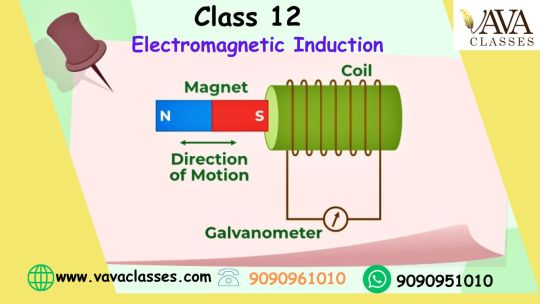
The key components of electromagnetic induction are:
1. Magnetic Field: A magnetic field is produced by a magnet or a current-carrying conductor. It is represented by lines of force that indicate the direction and strength of the field.
2. Conductor: A conductor is a material through which electric current can flow easily. It could be a wire made of copper, aluminum, or any other conductive material.
3. Relative Motion: There must be relative motion between the magnetic field and the conductor. This motion could be caused by the movement of the conductor through a stationary magnetic field or by changing the strength of the magnetic field around a stationary conductor.
When there is a change in the magnetic field (either through motion or variation in intensity), it induces an electromotive force (EMF) or voltage across the conductor according to Faraday's law of electromagnetic induction. This induced voltage causes an electric current to flow if the conductor forms a closed loop.
The magnitude of the induced voltage depends on several factors, including the rate of change of the magnetic field, the number of turns in the conductor (if it's a coil), and the material properties of the conductor.
Faraday's law of electromagnetic induction class 12
Faraday's law of electromagnetic induction, a fundamental principle in electromagnetism, is typically covered in physics curricula around the world, including in class 12 studies. This law, discovered by Michael Faraday in the 19th century, describes the relationship between a changing magnetic field and the induced electromotive force (EMF) or voltage in a conductor. Here's a simplified explanation suitable for a class 12 level:
Faraday's law states that the magnitude of the induced electromotive force (EMF) in a circuit is directly proportional to the rate of change of magnetic flux through the circuit. It can be mathematically expressed as:
EMF = - ΔΦ/ Δt
Where:
EMF is the induced electromotive force (in volts).
ΔΦ is the change in magnetic flux (in webers).
Δt is the change in time (in seconds).
Key concepts related to Faraday's law include:
1. Magnetic Flux (Φ): Magnetic flux is a measure of the quantity of magnetic field lines passing through a given area. It is calculated as the product of the magnetic field strength (B) and the area (A) perpendicular to the magnetic field:
Φ = B⋅A
2. Change in Magnetic Flux: According to Faraday's law, an induced EMF is produced in a circuit when there is a change in magnetic flux through the circuit. This change can occur due to either a change in the magnetic field strength, the area of the circuit exposed to the field, or the angle between the magnetic field and the circuit.
3. Lenz's Law: Lenz's law, a consequence of Faraday's law, states that the direction of the induced current (and hence the induced EMF) is such that it opposes the change in magnetic flux that produced it. In other words, the induced current creates a magnetic field that opposes the original change in flux.
Applications and demonstrations of Faraday's law and electromagnetic induction are often covered in class 12 physics courses, including examples such as transformers, generators, and electromagnetic devices like induction cooktops and wireless chargers. Understanding Faraday's law is crucial for comprehending many principles of electromagnetism and its practical applications in various technologies.
Class 12 Physics Applications of Electromagnetic Induction
Electromagnetic induction has a wide range of applications across various fields. Some of the most common applications include:
1. Electric Power Generation: Electromagnetic induction is the principle behind the operation of power plants. Generators utilize rotating coils within magnetic fields to convert mechanical energy into electrical energy. This process is the foundation of most electricity generation methods, including hydroelectric, thermal, and nuclear power plants.
2. Transformers: Transformers rely on electromagnetic induction to change the voltage levels of alternating current (AC) electricity. By varying the number of coils in the primary and secondary windings, transformers can step up or step down voltage levels efficiently, facilitating transmission and distribution of electricity across long distances.
3. Induction Cooking: Induction cooktops use electromagnetic induction to directly heat pots and pans. An alternating current is passed through a coil beneath the cooking surface, generating a magnetic field. When ferromagnetic cookware is placed on the surface, the magnetic field induces eddy currents within the cookware, producing heat and cooking the food.
4. Wireless Charging: Electromagnetic induction is employed in wireless charging systems for devices such as smartphones, electric toothbrushes, and electric vehicles. Charging pads or mats contain coils that generate magnetic fields. When a compatible device with a corresponding coil is placed on the pad, electromagnetic induction transfers energy wirelessly, charging the device's battery.
5. Metal Detection: Metal detectors utilize electromagnetic induction to detect the presence of metallic objects buried underground or hidden within other materials. When a metal object enters the detector's electromagnetic field, it induces eddy currents in the metal, causing a change in the field that can be detected by the device.
6. Eddy Current Braking: Electromagnetic induction is employed in eddy current braking systems, commonly used in trains, roller coasters, and industrial machinery. When a conductive material, such as a metal disc or rail, moves through a magnetic field, eddy currents are induced, creating resistance and slowing down the object's motion.
7. Eddy Current Testing: This non-destructive testing method uses electromagnetic induction to detect defects, cracks, or irregularities in conductive materials. By inducing eddy currents in the material and analyzing changes in the resulting magnetic field, flaws can be identified without damaging the material.
8. Magnetic Levitation (Maglev) Trains: Maglev trains use electromagnetic induction to levitate and propel the train along the track. Electromagnets along the track generate a magnetic field, which interacts with magnets on the underside of the train, causing it to float above the track and move forward without friction.
Conclusion:
The study of Electromagnetic Induction in Class 12 Physics offers a profound understanding of Michael Faraday's groundbreaking discovery and its practical applications. Throughout this chapter, students delve into Faraday's law and its mathematical formulation, exploring how a changing magnetic field induces an electromotive force in a conductor. By grasping concepts such as magnetic flux, Lenz's law, and the factors influencing induced EMF, learners gain insight into the operation of transformers, generators, and various electromagnetic devices. Class 12 students emerge from this chapter equipped with the knowledge to comprehend and appreciate the role of electromagnetic induction in numerous technological advancements, laying a strong foundation for further exploration in the realm of electromagnetism.
#class 12#science#physics#chemistry#class 8 online classes#class 8 tuition classes#class 9 tuition classes#class 9#class 10#class 11#organic chemistry#mathematics#maths#biology#vavaclasses
0 notes
Text
Unveiling the Wonders of Electrical Engineering
Electrical engineering stands as a cornerstone of technological advancement, driving innovation and progress in the modern world. This field, rooted in the principles of electricity, electronics, and electromagnetism, encompasses a vast array of applications, from powering homes and businesses to developing cutting-edge electronics and communication systems. In this article, we will explore the fundamental aspects, key principles, and diverse applications that make electrical engineering an indispensable force in shaping the future.
Foundations of Electrical Engineering
Electricity and Magnetism: At its core, electrical engineering revolves around the principles of electricity and magnetism. Understanding the behavior of electric charges, electromagnetic fields, and the interplay between electricity and magnetism forms the foundation for designing and analyzing electrical systems.
Circuit Theory: Circuit theory is a fundamental aspect of electrical engineering that deals with the study of electrical circuits. Engineers in this field design and analyze circuits to control the flow of electric current, ensuring the efficient transfer of energy.
Electronics: Electronics is a key branch of electrical engineering that focuses on the design and development of electronic circuits and devices. From transistors to integrated circuits, electronics plays a crucial role in creating the electronic gadgets and systems that have become integral to our daily lives.
Power Systems: Power systems engineering involves the generation, transmission, and distribution of electrical energy. Engineers in this domain work on designing power plants, developing energy-efficient technologies, and optimizing the electrical grid to ensure a stable and reliable power supply.
Key Principles in Electrical Engineering
Ohm's Law: Ohm's Law is a fundamental principle in electrical engineering that describes the relationship between voltage, current, and resistance in a circuit. This law is essential for understanding and predicting the behavior of electrical components.
Electromagnetic Induction: The principle of electromagnetic induction, discovered by Michael Faraday, is the basis for the operation of generators and transformers. It explains how a changing magnetic field induces an electromotive force (EMF) in a conductor, a phenomenon crucial for power generation and distribution.
Control Systems: Control systems engineering involves the design of systems to regulate and control the behavior of dynamic systems. This is vital in applications such as robotics, automation, and feedback control in various processes.
Applications of Electrical Engineering
Power Generation and Distribution: Electrical engineers play a pivotal role in designing and maintaining power generation plants and the infrastructure for transmitting and distributing electrical energy to homes, industries, and businesses.
Electronics and Communication: The design and development of electronic devices, communication systems, and information technology are central to electrical engineering. This includes smartphones, computers, telecommunication networks, and satellite systems.
Renewable Energy: Electrical engineers are at the forefront of the renewable energy revolution, working on the development of solar panels, wind turbines, and other sustainable technologies to harness and utilize clean energy sources.
Automation and Control Systems: In industrial settings, electrical engineers design and implement automation and control systems to enhance efficiency, safety, and precision in manufacturing processes.
Conclusion
Electrical engineering serves as the backbone of the technological landscape, powering the devices and systems that have become indispensable in our daily lives. Visit their website from the generation of electrical energy to the development of advanced electronics and communication technologies, electrical engineering continues to drive innovation, shape industries, and pave the way for a more connected and sustainable future. As we stand on the cusp of the next wave of technological evolution, electrical engineering remains at the forefront, leading the charge towards a brighter and more electrifying tomorrow.
0 notes
Text
Electromagnetic Induction
Electromagnetic Induction is a phenomenon that laid the foundation for countless technological advancements, is a captivating subject that delves into the interconnected world of electricity and magnetism. Let's embark on a journey to unravel the mysteries of this fascinating concept.
At its core, it refers to the generation of an electromotive force (EMF) or voltage in a conductor when exposed to a changing magnetic field. Discovered by Michael Faraday in the 19th century, this phenomenon revolutionized the way we harness and utilize electrical energy.
The key principle behind Electromagnetic Induction is Faraday's law, which states that the induced EMF is directly proportional to the rate of change of magnetic flux through a coil or conductor. In simpler terms, whenever a magnetic field around a conductor fluctuates, it induces an electric current.
Irevize is the backbone of numerous devices we encounter in our daily lives, from transformers and generators to inductors and electric motors. Understanding it is crucial for engineers and scientists, enabling them to design efficient electrical systems and devices.
Moreover, Electromagnetic Induction is pivotal in renewable energy sources like wind and solar power. Generators harness the kinetic energy of wind or sunlight, converting it into electricity through the principles of this study notes.
Electromagnetic Induction - Study Notes by irevize serve as a cornerstone in electromagnetism, powering the technological marvels surrounding us. By comprehending the intricacies of this phenomenon, we unlock the door to a world of innovation and sustainable energy solutions.
Visit Us: - Electromagnetic Induction
Contact us for any Query
Call @: 91 9717689100
Email @: [email protected]
Address: A-32b, Top floor, Vishwakarma Colony, New Delhi - 110044
0 notes
Text
Understanding The Basics Of Electrical Circuits

Electrical measuring instruments are essential tools for monitoring, measuring, and analyzing electrical circuits and systems. These instruments play a crucial role in maintaining the safety, accuracy, and efficiency of electrical systems in various industries like construction, manufacturing, and electrical engineering.
This blog will help you to understand the different electrical measuring instruments, their applications and how to use these instruments correctly to get accurate readings. You can also read our blog – A Complete guide to electrical units of measurement here.
What is an Electrical Circuit?
Electricity is a huge part of our lives now, without which it becomes impossible to access lights and fans, charge our many devices or even cook on our induction stoves. Come to see it, we have come a long way with electricity, but how well do we know it? We will start with the basics of an electrical circuit – the most integral part of electricity.
An electrical circuit is a closed loop for transmitting an electric current via electrical or magnetic fields. The electric current is made up of the flow of electrons across the path. Let us look at the fundamentals of an electric circuit to understand it better:
These electrons enter the circuit through the “source” which could either be a generator or a battery. The source sets up an electrical field, generating the electromotive force which provides energy to the electrons.
Electrons then leave the circuit through the load or output, reaching the earth’s ground, thus completing a closed path. A load may be a simple home appliance like a refrigerator, television, or lamp or a heavier load, such as one on a hydroelectric power generating station.
A simpler example of an electric circuit would consist of a source like a battery, which provides the necessary energy for the flow of electrons, and a conducting medium such as a wire, with the light bulb being the output/load. Read more
0 notes
Text
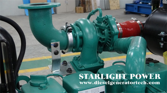
Cummins Diesel Generator Dirt Removal Methods
During the operation of Cummins diesel generator, there must be some dirt. How to remove those dirt? In this article, Starlight Power Generation Equipment Co., Ltd. will briefly introduce some methods for Cummins diesel generator to remove dirt.
1. Oil washing method is often used to remove oil stains
General parts are cleaned with diesel and dried with compressed air after cleaning. Detailed parts can be cleaned with diesel or petroleum. But after cleaning with diesel, if not repaired or assembled quickly, the parts should be soaked in diesel again to prevent rusting.
2. For parts with high oil stains, chemical cleaning can be used when equipment conditions permit. The parts can be placed in an alkaline solution, heated to 70-90 ℃, soaked for 10-15 minutes, removed, and washed clean with clean water (preferably hot water), and then dried with compressed air.
In order to prevent corrosion of non-ferrous metal parts, the formula of the solution should be different from that of steel parts. When cleaning, the formula should be selected based on the material and surface quality requirements of the parts, as well as the quantity of stored drugs.
Key points for applying cleaning agents:
1. Control the preparation method and concentration of cleaning solution.
2. Control the cleaning temperature and heating method well, and strictly control the temperature during manual cleaning.
3. To adopt appropriate mechanical means, the cylinders of the Cummins diesel generator work in a certain order, and the thrust that affects the piston becomes the force that drives the crankshaft to move and transform through the connecting rod, thus driving the crankshaft to twist. Applying the principle of 'electromagnetic induction', Cummins diesel generator will output induction electromotive force, and current can be generated through the closed load circuit. This article only describes the operation principle of Cummins siesel generator. In order to obtain an applicable and stable power output, a series of diesel engine and generator control, protection devices and circuits are also needed. Brushes and wipes can be used for manual cleaning. Cummins siesel generator refers to the mechanical equipment that converts the energy of other situations into electrical energy. It is driven by water turbines, steam turbines, diesel engines or other power machines to transfer water flow, air flow, The energy generated by fuel combustion or atomic Nuclear fission is converted into mechanical energy and transmitted to the generator, which then converts it into electrical energy. When there is serious oil stains or carbon deposits, a steel wire brush can be used for cleaning.
4. Before cleaning, there should be a certain amount of soaking time to meet the needs of dampness, infiltration, and exudation.
5. Cleaning can be divided into coarse washing and fine washing. When the oil stains on the cleaning solution after fine washing are not severe, the floating oil stains on the upper layer can be scraped off and reapplied.
As a professional diesel generator manufacturer, we always insist on using first-class talents to build a first-class enterprise, create first-class products, create first-class services, and strive to build a first-class domestic enterprise. If you would like to get more information welcome to contact us via [email protected].
0 notes
Text
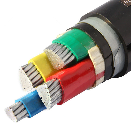
Armored cable grounding Reason for
MV ABC cable
The purpose of armored cables is to increase mechanical strength and prevent mechanical damage. Usually, the armor layer of armored cables needs to be grounded. Why do we need to ground both ends?
Because when the insulation of the cable is damaged, the armor layer will become charged. Armored cables have no interference issues, and our grounding purpose is safety. Grounding at both ends can reduce grounding resistance, increase fault current, and ensure more reliable electrical protection.
The specific analysis is as follows:
If the steel strip pierces a certain phase of insulation in the middle of the cable, and the outer protective layer is intact, the steel strip is in a charged state but cannot be detected, which is easy to cause an electric shock accident; If grounded, it can drive the protection device to trip.
Although the steel strip of the inner armored cable is not exposed, when the three-phase current is unbalanced, the armored layer may discharge due to the induced electromotive force, and in severe cases, the protective layer may be burned. When the armor layer is grounded, its potential with the ground is flattened, leading to discharge.
After grounding the copper tape shield as part of the core insulation shielding layer, it can not only equalize the potential of each core shielding layer, but also reduce the potential difference between the copper tape and the steel armor to avoid discharge.
If not grounded, the current passing through the cable will be large enough to generate eddy currents in the armored steel strip, which will generate heat. The current carrying capacity of the cable will decrease, and the cable will generate heat again, leading to short circuit or burning of the cable.
0 notes
Text
Faraday's EMF Law
User
Faraday law
ChatGPT
Faraday's law refers to a set of fundamental principles in electromagnetism, which describe the relationship between a changing magnetic field and the induced electromotive force (EMF) or voltage in a conducting loop or circuit. The law is named after the English scientist Michael Faraday, who made significant contributions to the study of electromagnetism in the 19th century.
There are two main laws associated with Faraday's law:
Faraday's First Law (Faraday's Law of Electromagnetic Induction): It states that when there is a change in the magnetic field through a loop of wire, an electromotive force (EMF) is induced in the wire. The magnitude of the induced EMF is proportional to the rate of change of magnetic flux through the loop. Mathematically, it can be expressed as:
EMF = -dΦ/dt
where EMF is the induced electromotive force, dΦ/dt is the rate of change of magnetic flux, and the negative sign indicates the direction of the induced current according to Lenz's law.
Faraday's Second Law (Faraday's Law of Electrolysis): It states that the amount of chemical reaction occurring at an electrode during electrolysis is directly proportional to the quantity of electric charge passed through the electrolyte. Mathematically, it can be expressed as:
Q = I * t
where Q is the quantity of charge passed, I is the current flowing through the circuit, and t is the time for which the current flows.
These laws have significant applications in various fields, including power generation, electric motors, transformers, and the functioning of many electronic devices. They form the basis for understanding the principles of electromagnetic induction and are fundamental to the study of electromagnetism.
Applications of Faraday's Law
Transformers.
Enlistment engines.
Electric generators.
Electromagnetic shaping.
Corridor Effect meters.
Current Clamp.
Enlistment cooking.
Attractive stream meters.
Advantages of Faraday's Law
The main advantage of Faraday's law is that it connects the produced mass with the generated electrical charge.
Faradays Law of Electrolysis - an overview | ScienceDirect Topics
Disadvantages of Faraday's Law
Disadvantages: One of the disadvantages of electromagnets is that they heat up very fast and due to this heat generation lose of electrical energy is very much. A continuous power supply requires maintaining the constant magnetic field.
0 notes
Text
How does the DC-DC converter work?
DIY voltage-boosting LED driver
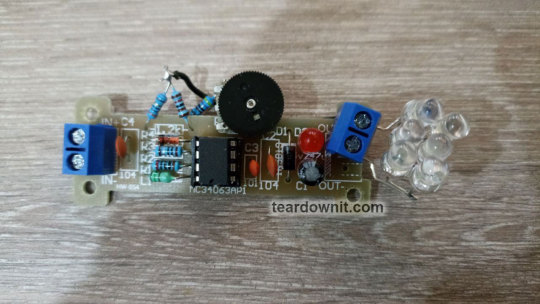
How is it assembled?
How do you convert an existing one to suit your needs?
Hi! My secret helper wrote this post.
She's in love with electronics, guitars, and cats.
Kevin (teardownit.com editor)

ANOTHER secret helper.
This guy can't write posts.
We will consider the principles of how a step-up (boost) converter operates, and most importantly, current and voltage feedback, using a homemade LED flashlight as an example.
Pulse power converters (or voltage converters, as they are generally called) have long been an integral part of electronic technology. The fact of the matter is, chemical current sources such as batteries and accumulators produce low voltage, while many other devices, primarily those based on vacuum and gas-discharge lamps, require high voltage.
The basis for today's DIY kit is the ready-made ICSK034A from icstation.com. This is a kit for assembling a 5 to 12 volt step-up converter.

This isn’t just a joule thief, but a stabilized converter that maintains a predetermined voltage at the output. However, my goal today is not to make a 12V power supply, instead, I want to make an LED flashlight with continuously variable brightness. In other words, I’m going to make a controlled boost current regulator for the LED.
So, today we are going to study the feedback of pulse power converters and as a result, we will be able to build a converter with the properties that we need. Or we can modify an existing converter to the one we need, specifically, one where we can add or change the current or voltage feedback. Or we can make the existing feedback controllable, i.e. add the possibility of reconfiguration.
The main component of a step-up converter is the coil. In electronics, coils and capacitors are called reactors because there is a reaction, i.e., a counteraction.
Converter operating principle
The step-up voltage converter works as follows. The power consumer is connected to the power supply through a coil and a diode. If nothing happens, the voltage at the consumer is equal to the input voltage minus the drop on the diode and the coil's active resistance.
But after the coil, there is a switch that closes the circuit, which consists of the power supply and the coil. In a real converter, this would be a bipolar junction transistor (BJT) or a field-effect transistor (FET). This can also be a separate transistor or one that’s integrated into a chip.
When this switch closes the circuit, the current in the coil increases. The active resistance of the coil is usually low, so it should be turned on briefly so as not to burn anything out.
When the switch breaks the circuit, the coil tries to keep the current constant. Now there is no path for the current to take through the switch, so it will go through the diode to the power consumer instead.
When the circuit of the switch is opened, the current decreases. At the moment the current decreases, an electromotive force (EMF), i.e. voltage, is generated in the coil. Its polarity causes the current to flow in the same direction as it did when the switch was turned on.
That is, this additional voltage is added to the EMF of the power source. Therefore, the power consumer receives more voltage than the original source provides. This is the reason why this type of converter is called a “boost” converter.
The capacitor smoothes out voltage spikes in parallel to the power consumer. When the coil generates an electromotive force, it is charged to a higher voltage. When the coil is charged with current through a switch, the capacitor gives the stored charge to the power consumer.
These two reactors, or integrators, the coil, and the capacitor are integral parts of the step-up conversion process and are mandatory components of the converter.
A diode is also mandatory, as it prevents the capacitor from discharging through the switch. The diode only allows the current to flow in one direction. If the power consumer is a battery, the diode prevents it from discharging through the switch.
Properties of the inductor coil
The voltage at the output of the inverter depends on the discharging capacitor’s current consumption and its charging energy given by the coil in each duty cycle. The magnetic field energy of the coil with current is equal to the inductance of the coil multiplied by the square of the current in it.
For its part, the strength of the current running through the coil depends on the voltage of the original source and the time during which it was charged. This is because as magnetic energy accumulates, the current strength increases gradually in the coil.
We can observe that the current gradually increases. The oscilloscope shows the voltage on the series resistor, which depends on the current as per Ohm's law.
A resistor that converts current to voltage for the purpose of measuring the current or current feedback is called a shunt.
We can observe a beautiful exponential fragment of the magnetization curve because the coil is charged with current just like a capacitor is charged with voltage. When we break the circuit, we can observe the neon bulb light up.
It needs at least 50 volts to break through the interelectrode gap and establish a glow discharge. It’s even closer to 80 volts. The battery voltage is 3 volts. You can observe how the coil’s voltage increases by several orders of magnitude.
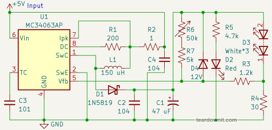
Study the diagram
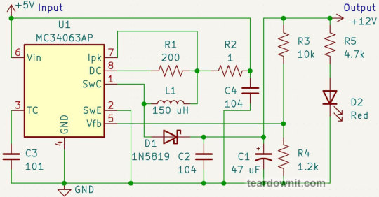
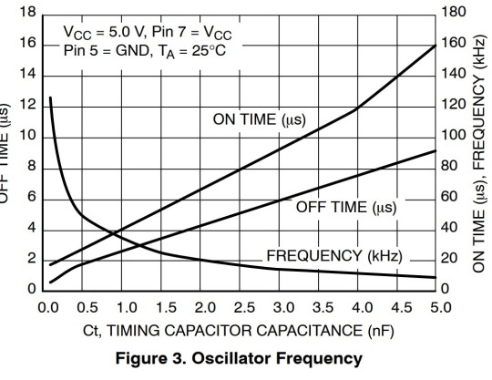
Now let's look at the circuit of the converter. It is built on the MC34063 chip. The capacitor C3 determines the frequency of the oscillation. The capacity of 100 picofarads corresponds to the highest frequency of this chip, which is 100 kilohertz. That is 100,000 on-and-off actions per second. Our electronic friends sure know how to work fast.
The resistor R2 determines the peak current of the output transistor, i.e. our switch. It is a shunt. When the voltage on it reaches 300 millivolts, the chip closes the transistor, thus stopping the further increase of current. 300 millivolts on a 1 Ω resistor will be at 300 milliamps current.
The resistor R1 limits the base current of the output transistor. It is not a shunt because this resistor does not turn the current into a voltage that controls anything, but simply limits the current according to Ohm's law.

The small LED D2 has two functions. It is both an indicator of the instrument’s operation and most importantly, the idle load.
An idle load is a mandatory part of any inverter or stabilizer since neither can operate when no power is being consumed because there would be nothing to convert or stabilize.
Now for the best part. Any stabilizer has a feedback input. The stabilizer controls the movement of something, such as an electric current, in such a way that the feedback voltage always equals a certain value.
The linear voltage regulator opens the output transistor so that the voltage between the output and the feedback pin is 5 volts if it is a 7805, or 1.25 V in the case of an LM317.
All excess voltage falls on the line stabilizer transistor. This transistor is connected in series with the power consumer. Therefore the current through them is the same.

Let’s say that it’s one ampere, for example. The power supply voltage is 9 V, and the power consumer voltage is 5 V. That is a four-volt drop on the transistor.
Power is equal to current multiplied by voltage. Therefore, the total consumption from the power supply would be 9 watts. But the consumer only gets 5 of these watts. Four watts are lost on the stabilizer transistor, which heats it.
This is a waste of energy, which is especially bad in conditions of autonomous power supply from batteries or generators. The line stabilizer also needs a heat sink to cool it, which comes with additional volume, weight, and cost.
Unlike a linear converter, a pulse converter opens and closes the output transistor completely. When the transistor is fully open, there is a small voltage drop across the transistor, so less heat is generated. The pulse converter has the capability of increasing the voltage, while the linear converter can only decrease it.
So, the feedback input of this pulse chip is its fifth pin. The MC34063 controls the duty cycle so that it holds 1.25 volts on the feedback pin.
The duty cycle is the ratio of the time interval when the transistor is open to the total period of oscillation.

In the schematic, the voltage divider R3R4 is connected to the feedback pin. The resistor R4 has a resistance of 1.2 kΩ. The voltage across it is nearly 1.2 volts, so the current will be one milliampere.
Therefore, the resistor R3, with a resistance of 10 kΩ, will have a voltage of 10 V. 10 + 1.2 = 11.2, that is, almost 12 V at the output of the inverter. This is the voltage feedback.
To get the current feedback, you need a shunt the voltage of which is 1.25V at the desired current. The kit page on the developer's website, http://www.icstation.com/icstation-step-module-boost-converter-power-supply-module-p-4151.html, says that the converter can handle 60 milliamps at five volts on the input and 12 volts on the output.
I plan to use an LED matrix with an operating voltage of about 10 volts. This matrix consists of three white LEDs connected in series. It turns out that the output voltage of the converter will be the same: 10V at the LED plus 1.25V at the shunt.
However, I won’t be powering the converter from a five-volt USB power bank, but rather from a lithium battery. Its minimum voltage is 3.7 V.
The lower the input voltage is, the higher the load on the coil and the transistor of the step-up converter.
The chip in this kit is quite powerful, but the coil is weak. Therefore, it is possible to draw a current of (60/5)*3.7 = 44 milliamps from the output of the inverter. Hence, the shunt resistance should be 30 Ω.

This huge LED can draw up to 900 mA, but it needs a heat sink in this case. If I were to use a more powerful coil, it would be possible to make a step-up converter with a higher output current.
Accordingly, I could set a higher peak current with the resistor R2, but not more than 1.5 amperes, because this is the limit for our chip.
I also want to add gradual brightness control. To this end, I won’t connect the shunt directly to the feedback input, but with a 1.2 kΩ resistor. The feedback input of the chip has a high resistance, so this resistor will not change anything on its own.

We’ll add a 50 kΩ variable resistor and a 5 kΩ ordinary resistor in series to prevent a direct connection of the feedback pin to the inverter output.
Now the feedback voltage will be equal to the sum of the shunt voltage and the additional 1.2 kΩ resistor. The chip keeps the feedback voltage constant. It will always be at 1.25 volts.
Therefore the voltage at the shunt, and therefore the LED current, will be lower by the value of the voltage at the additional resistor. This voltage depends on the current running through the variable resistor.
If this current value is one milliampere, the shunt is left with zero volts in total. In other words, the LED is not powered.
Everyone, or at least nearly everyone, knows that LEDs are powered by current; the higher the current, the brighter the light. At the same time, the voltage of the LED remains practically constant at different current values.
Sometimes LEDs are even used as stabilizers, i.e. voltage regulators. Thus, we’ll consider that the voltage across these three resistors (50k, 5k, and 1.2k) is ten volts.
If the variable resistor knob is in the 0 Ω position, the resistance of this circuit is 6.2 kΩ. The current is above 1 milliampere, that is, the LED is off.
If the knob is in the 50 kΩ position, the total resistance is 56 kΩ and the current is 180 microamperes.
This is eighteen percent of one milliampere. Therefore, the shunt resistance can be reduced by eighteen percent. So we get 26 Ω for the shunt.
As a result, we get a brightness controller. If the LED is always connected to the output of the inverter, nothing else needed to be done. The LED will limit the output voltage of the inverter.
If there’s no LED or the output voltage is lower than the operating voltage of the LED, that is, it is closed and does not take part in the operation of the circuit, the brightness control circuit operates as voltage feedback.
The current of the divider is one milliampere. Specifically, the number of volts at the output is equal to the number of kΩ of the total resistance of the divider. The lowest voltage output is 6.2 volts. This is acceptable.
However, the highest voltage is 56 volts, which is too high. This can damage the electrolytic capacitor and the diode.
What can we do with the voltage feedback so that it doesn't interfere with the brightness controller? A Zener diode can save the day. This is a special diode that is connected in the reverse direction.
If the voltage on it is lower than its operating voltage, it stays closed and does nothing. If the voltage reaches the operating voltage, it opens and stabilizes the voltage.
In other words, when the LED is plugged in, the Zener diode doesn’t interfere with the flashlight’s operation. When the LED is not connected, the output voltage will be 12 + 1.25 = 13.25V. This voltage may be lower, depending on the position of the brightness control.
Now we can assemble the inverter with the circuit modifications that we have now developed.
The 900-milliampere matrix refused to work from the converter. It needs at least 200-300 mA. The matrix just eats up the small current and doesn’t even glow.
Therefore, I made a matrix of 2p3s (two in parallel, three in series) from ordinary 5mm white LEDs. Thus, the allowable current is 2*20 = 40 mA and the operating voltage is 3*3.3 = 10 V. I didn’t decrease the shunt resistance to 26 Ω, but left it at 30. Moreover, I had just the right resistor in stock.
The video shows tests of the resulting driver at different supply voltages. The brightness adjusts perfectly. The boost converter actually starts working at 1.75 volts of the input supply which is much sooner than at the 3 volts that the chip datasheet proclaims.
With an input voltage of 1.8 V, there’s already enough voltage at the output for the LED matrix to start glowing.
To measure the power conversion efficiency, I connected voltmeters and ammeters to the input and output. The results can be observed in the following table, which shows the measurements at different input voltages and brightness control positions.

The abundance of information can look intimidating, especially in its raw form. However, we only need to look at the columns that display the input voltage, output power, and efficiency. Electrical power is equal to the product of voltage and current, while efficiency is the ratio of output power to input power.

This is a graph that shows efficiency vs. input voltage. It’s much more comprehensible than the table. The graph shows that the converter works more efficiently when the supply voltage is higher than 3.5 volts. We can also see the smooth lines corresponding to the turns of the LED brightness control knob, i.e. the output current of the converter.

And this is a graph of efficiency vs. output power. Judging from this, we can say that in the case of our flashlight, the higher the power, the more efficient the conversion is. Again, we see smooth lines, but this time they’re "drawn" by turning the supply voltage regulator.
Why is the efficiency of our flashlight so low? First of all, the shunt loses as much as 1.25 volts. This is more than 12 percent of the LED matrix’s voltage, so it’s more than 12 percent of the efficiency.
Secondly, the supply current of the red indicator LED is comparable to the current of the matrix. At the same time, this indicator is not powered by the input, but by the output. Its current draw resistor R5 simply converts part of the power consumption into heat.
Furthermore, the voltage drops on the Schottky diode D1 and the output power switch that’s built into the MC34063 chip. This switch is a bipolar transistor.
If we were to use a more modern DC-DC converter chip with a MOSFET transistor as an output switch, a lower feedback voltage, and correspondingly, lower shunt losses, the efficiency of the flashlight would be much higher.
DC-DC converters with a synchronous converter that uses a MOSFET instead of a Schottky diode are even more advanced than that.
Alternatively, we could add a shunt signal amplifier, or reduce its resistance and shift up the bias range from the brightness regulator. For example, this could be done in such a way that at maximum LED current, 0.25 volt falls on the shunt and 1 volt comes from the regulator, then the brightness is at its maximum, up to 1.25, then the LED doesn’t shine at all.
Conclusion
In conclusion, today we found out that the world of DC-DC converters is diverse and complex, but it is possible to achieve the desired result through simple means.
To do this, it’s enough to understand how feedback works and how to form the feedback voltage.
A shunt can be used to convert the output current to voltage and, as a result, get a current regulator.
The output voltage can be stabilized with an output voltage divider.
The output voltage can be limited by a Zener diode, without interfering with the current regulator.
With a bias current through a variable resistor, it’s possible to add the desired value to the feedback voltage, making the current regulator adjustable.
Thank you for your attention!
Demo video
youtube
1 note
·
View note
Text
"The Importance of IC Sockets and Terminal Blocks in Electronic Design"
Integrated circuits (ICs) are the building blocks of Bodoni font electronic devices. These tiny chips can contain millions of transistors, allowing for undefined functionality in a small form factor. However, ICs are not standalone components - they require connections to unusual components in the circuit to operate properly. This is where IC sockets and terminal blocks come in.
IC sockets are old to securely mount ICs onto a printed undefined board (PCB) without the want for soldering. This makes it easy to replace a faulty IC or upgrade the circuit without damaging the PCB. Sockets also allow for testing and prototyping of circuits before final assembly. They come in various sizes and configurations to accommodate different Intelligence Community packages.
Terminal blocks, on the strange hand, are used to connect wires or unusual components to the undefined board. They supplya procure and reliable connection that can be easily disconnected when necessary. Terminal blocks come in many shapes and sizes, from single-terminal strips to multi-position blocks, and can handle a straddle of current and electromotive force ratings.
The use of United States Intelligence Community sockets and terminal blocks in electronic design has some benefits. Firstly, they offer flexibility and ease of use during prototyping and testing. With sockets, designers can switch out ICs or qualify circuits without damaging the PCB, which savesclock and money in the long run. Terminal blocks also make it easy to connect and unplug wires or components, reducing the risk of damage or short-circuit circuits.
Another advantage is the cleared reliability of the final product. National Intelligence Community sockets ensure that the IC is securely affixed and protected from mechanical stress, reducing the likeliness of unsuccessful personsundefined to physical damage. Terminal blocks provide a robust and steady-going connection that puts upresistance to environmental factors such as temperature changes and vibration.
Furthermore, the use of IC sockets and depot blocks can streamline the meeting place process. With pre-mounted sockets and terminal blocks, the time and effort required for hand-soldering or wire-wrapping connections are eliminated. This can result in quicker assembly multiplication and improved production efficiency.
In conclusion, IC sockets and terminal blocks play a material role in Bodoni font electronic design. They offer flexibility, ease up of use, improved reliability, and streamlined assembly processes. As such, designers should carefully look at the use of these components in their electronic circuits to optimise their plan and ensure the highest level of performance and reliability.
0 notes
Text
Understanding the Differences between High Voltage DC Power Supply and Low Voltage High Current DC Power Supply
When it comes to choosing a District of Columbia power supply, there are II main types to consider:high voltage DC power supply and low voltage high stream District of Columbiasuper power supplies. Sympathy for the differences between these two types of power supplies can help you choose the right one for your needs.
High voltage DC world power supplies are designed to provide a senior high school voltage output, typically in the straddle of someone C volts or more. These power supplies are often used in applications that require high voltage, much as in natural philosophy devices, check-up equipment, and scientific research. They are designed to cater a stable and dependable output voltage, even belowhigh load conditions.
Low voltage high current DC supply, on the other hand, is premeditated to provide a high current production at a low voltage. These power supplies are much used in applications that need a large amount of current, such as in welding, battery charging, and electroplating. They are designed to provide a stable and reliable yield current, even under senior high load conditions.
One of the main differences between senior high voltage DC power supplies and moo voltage high current DC power supplies is their output voltage and current capabilities. High voltage DC power supplies are designed to provide a high output voltage, spell low voltage high flow DC power supplies are designed to cater a high yield current. Depending on your application, you may require one or the other, or both.
Another difference is their design and construction. High electromotive force DC power supplies are typically designed with insolent and safety features to prevent electrical shock and damage to the power cater or other equipment. They may also have additional features much as remote control and monitoring capabilities. Low electromotive force high current District of Columbia power supplies, on the other hand, are typically designed to be rugged and durable, with high-school current-carrying capabilities and protection against short circuits and overloads.
In conclusion, when it comes to choosing a DC power supply, it is of import to consider your specific practical application and requirements. Senior high voltage DC great power supplies are designed to provide a senior high schoolproduction voltage, while low voltage high current DC power supplies are studied to provide a high production current. Depending on your needs, you may requireone or the other, or both. Working with a reputable supplier can help you witness the right DC power supply for your needs.
0 notes
Text
Transformer Formula
In order to transfer electrical energy between two circuits, a transformer converts the rotation of one shaft into the other. It is a component of a circuit whose main duty is to transform electromotive forces (EMFs) into other forms. Step-up transformers are the most prevalent type of transformer, but voltage regulators and step-down transformers are also available.
In this article, the transformer formula is explained with examples.
Any device that changes one form of energy into another is sometimes referred to as a “transformer” in a more general sense. In actuality, this term only applies to electrical transformers that transform voltage or power at one frequency into voltage or power at a different frequency. In some cases, it also applies to non-electrical devices that use transducers rather than conductors, such as turbogenerators and methanol converters. The transformer formula can be easily understood by the end of this article.
0 notes
Text
EV Charger charging principle and method
There are two ways to charge electric vehicles, AC charging and DC charging, both of which have a large gap in technical parameters such as current and voltage. The former has a lower charging efficiency, while the latter has a higher charging efficiency. Generally speaking, the "slow charging" that people often say uses AC charging, while the "fast charging" mostly uses DC charging.
EV Charger charging principle
The charging pile is fixed on the ground, uses a special charging interface, and adopts a conduction method to provide AC power for electric vehicles with on-board chargers, and has corresponding communication, billing and safety protection functions. Citizens only need to buy an IC card and recharge it, and then they can use the charging pile to charge the car. the
After the electric vehicle battery is discharged, direct current is passed through the battery in the opposite direction to the discharge current to restore its working capacity. This process is called battery charging. When charging the battery, the positive pole of the battery is connected to the positive pole of the power supply, and the negative pole of the battery is connected to the negative pole of the power supply. The voltage of the charging power supply must be higher than the total electromotive force of the battery.
EV Charger charging method
There are two charging methods: constant current charging and constant voltage charging.
Constant current charging method
The constant current charging method is a charging method that keeps the charging current intensity constant by adjusting the output voltage of the charging device or changing the resistance in series with the battery. The control method is simple, but because the acceptable current capacity of the battery gradually decreases with the progress of the charging process. In the later stage of charging, the charging current is mostly used for electrolyzing water, generating gas, and causing excessive gas output. Therefore, the stage charging method is often used.
Constant voltage charging method
The voltage of the charging power source maintains a constant value throughout the charging time, and the current gradually decreases as the battery terminal voltage gradually increases. Compared with the constant current charging method, its charging process is closer to the optimal charging curve. Fast charging with constant voltage, because the electromotive force of the battery is low at the initial stage of charging, the charging current is very large, as the charging progresses, the current will gradually decrease, so only a simple control system is needed.
0 notes
Text
Electromagnetic Induction - Unveiling the Wonders of Electromagnetic Induction
Electromagnetic Induction is a phenomenon that laid the foundation for countless technological advancements and is a captivating subject that delves into the interconnected world of electricity and magnetism. Let's embark on a journey to unravel the mysteries of this fascinating concept.
At its core, it refers to the generation of an electromotive force (EMF) or voltage in a conductor when exposed to a changing magnetic field. Discovered by Michael Faraday in the 19th century, this phenomenon revolutionized the way we harness and utilize electrical energy.
The key principle behind Electromagnetic Induction is Faraday's law, which states that the induced EMF is directly proportional to the rate of change of magnetic flux through a coil or conductor. In simpler terms, whenever a magnetic field around a conductor fluctuates, it induces an electric current.

Irevize is the backbone of numerous devices we encounter in our daily lives, from transformers and generators to inductors and electric motors. Understanding it is crucial for engineers and scientists, enabling them to design efficient electrical systems and devices.
Moreover, Electromagnetic Induction is pivotal in renewable energy sources like wind and solar power. Generators harness the kinetic energy of wind or sunlight, converting it into electricity through the principles of this study notes.
Electromagnetic Induction - Study Notes by irevize serve as a cornerstone in electromagnetism, powering the technological marvels surrounding us. By comprehending the intricacies of this phenomenon, we unlock the door to a world of innovation and sustainable energy solutions.
Visit Us: -Electromagnetic Induction
0 notes
Text
power system stability service
power system stability service
Power System Stabilization Services
To maintain the stability of the electrical system, the dynamics of the disturbed system must be studied Stability is the ability of an electrical system to return to normal or stable performance after a disturbance.
From a traditional perspective, power system instability can be thought of as loss of synchronization (i.e. some synchronous motors reverse phase) when the system is disturbed by some sort.
constant state stability
Steady-state behavior relates to how a synchronous motor responds to an increasing load This is primarily to determine the highest machine load level that can be achieved while maintaining synchronization. Stability in change.
Dynamic power system stability service is the response of a system to oscillations caused by small shocks If these oscillations do not exceed a certain amplitude and disappear immediately, the system is considered dynamically stable.
When the amplitude of these oscillations continues to increase, the system becomes dynamically unstable Connections between control systems often cause this type of instability.
temporarily stable
Transient stability is the ability to withstand sudden and potentially large changes in rotor speed, power angle, and power delivery. Transient stability is a transient phenomenon, which usually occurs within seconds.
The main area of research on the stability of electrical systems is rotor stability This requires certain assumptions, including a stability analysis that takes into account balanced three-phase systems and balanced disturbances.
The machine frequency rarely deviates significantly from the synchronous frequency.
During generator short circuits, high-frequency currents and DC offsets occur. However, it has been neglected when studying stability.
The load and network impedance are steady states. Thus, the power flow equation can be used to determine voltage, current, and current.
Ways to increase the stability limit
The maximum power that can be transferred between the alternator and the engine is directly proportional to the product of the internal electromotive forces of the two devices and inversely proportional to the line reactance The steady-state limit increases due to two factors:
The maximum power that can be transferred between two machines increases because the internal electromotive force is increased by increasing the power of the generator, motor, or both As the amount of internal EMF increases, the load angle decreases further.
Reduced Transfer Reactance: Reduce the reactance by lengthening the parallel lines connecting the transfer locations. Using bundled conductors is another way to reduce line reactance. The reactance can be reduced by using a capacitor in series with the line.
Powertrain components work with synchronous machines. They must always be synchronized to guarantee the stability of the electrical system When a failure occurs, the system generates a force that allows it to resume stable or normal operation.
In a power plant, several synchronous generators are connected to a bus with the same frequency and phase sequence as the generators, Therefore, generators must be synchronized with the busbar throughout generation and transmission to ensure reliable operation, For this reason, the term "power power system stability service" is often used to refer to synchronous stability, the ability of a system to return to synchronization after disturbances such as load switching or line transients.
The power system stability service limit is an additional factor that must be taken into account to fully understand stability. Stability limits identify the maximum power that can flow through specific areas of the system that are subject to line interruptions or insufficient power flow After reviewing terms related to power system stability, let’s take a look at the different categories of stability. The response of synchronous motors to disturbances is the main factor determining the stability of the system. Depending on the size of the disturbance, the stability of the power system can be divided into two categories.
Why is frequency stability analysis necessary?
The purpose of a frequency power system stability service study is to show how frequency source wobbles in the frequency and time domains The operation and design of power systems must consider frequency stability, especially in light of recent increases in load demand Electrical systems must now take load shedding-generation balancing into account to avoid system islanding. The stability of the system can be judged from the frequency point of view. It is now possible to effectively identify the threshold above which the protection device prevents frequency load shedding Since island networks are vulnerable to various interruptions, such as loss of generation or load, frequency stability is critical.
What does frequency stability analysis involve?
The reference widespread for frequency balance evaluation is IEEE Standard Definitions of Physical Quantities for Fundamental Frequency and Time Metrology, or IEEE Standard 1139-1999.
Typically, a frequency balance evaluation is carried out on an unmarried tool instead of a set of associated devices. The (finite) populace beneath neath evaluation is normally believed to be the output of the tool, which exists earlier than and after the particular information set turned into observed. Additionally, it's miles normally believed that the tool's stochastic residences are constant (each desk-bound over the years and ergodic over their populace).
If the evaluation famous is untrue, it is probably vital to partition the information report so that you can get beneficial results. Before studying the noise, it's miles often most excellent to symbolize and put off deterministic factors like frequency flow and temperature sensitivity. The handiest manner to address environmental effects is to take them out of the take a look at the environment. Additionally, it's miles assumed that the information is freed from instrumental outcomes and frequency reference instability. Creating outputs on the longest in all likelihood averaging intervals to reduce down on taking a look at time and value is a not unusual place hassle for time area frequency balance studies. In maximum cases, the evaluation time isn't always as important.
Data Accuracy
The exam of frequency balance information includes most effective a small number of numerical precision problems. However, segment information for a distinctly strong frequency supply with a full-size frequency offset is an exception. The frequency offset may be represented through an immediate line withinside the uncooked segment information, and the instability statistics are located withinside the mild deviations from the line. Unless the frequency offset is removed by deducting a linear issue from the uncooked segment information, a massive quantity of digits needs to be employed. The quadratic segment period is difficult to the identical issues (linear frequency flow).
Outlier Identification
Although the definition of an outlier is rather subjective, it's miles vital to become aware of and get rid of such factors primarily based totally on their divergence from the information's median and the use of a deviation restriction expressed in phrases of the median absolute deviation. This is a dependable approach for locating an outlier, that's eventually modified to a gap. This technique may be used iteratively through an automated outlier removal technique, which needs to be a complement to eye evaluation of the information, now no longer a substitute for it.
Conclusion
A well-designed energy machine ensures reliable overall performance and will increase plant availability beneath neath all running scenarios, such as brief occasions like motor starting, non-linear loads, and generator failure. Significant losses, such as outages, malfunctions, negative energy quality, and Arc Flashover, may be because of a machine that turned poorly built.
A stable and secure electric delivery may be completed thru the examination of energy systems. The crucial clearance time of circuit breakers, voltage levels, and machine switch ability can all be decided thru balance studies. Contact us these days for greater statistics!
0 notes
Last Seen Blogs

dershalovestory-blog
Everything Dersha

mikumoduleoftheday
Running on Queue

lostsoulsandmutineers
the moss in my lungs

gbstampz
GBstampz

chbgigi
gigi