#VHDL Introduction
Text
youtube
VHDL Tutorial : Your First VHDL Design: VHDL Entity & Architecture - A Beginner's Guide
Welcome to the ultimate beginner's guide for Your First VHDL Design! In this video, we will dive into the fundamentals of VHDL Entity and Architecture and provide you with a comprehensive understanding of the topic. Whether you are new to VHDL or looking to refresh your knowledge, this guide is designed to help you get started and pave your way to becoming an expert VHDL designer. In this tutorial, we will cover the basics of VHDL, starting with the VHDL Entity and its crucial role in the design process. You will learn how to define and describe the inputs and outputs of your VHDL design using the Entity section, providing the necessary specifications for your project. Moving on, we will explore the VHDL Architecture, which defines the actual implementation of your design. Through a step-by-step walkthrough, you will discover how to construct the architecture block by block, ensuring a well-structured and functional VHDL design. To make the learning experience more practical, we will dive into real-world examples and demonstrate each concept using a popular VHDL software tool. You'll witness the transition from theory to practice, gaining hands-on experience in VHDL design. With this beginner's guide, you'll not only grasp the essentials of VHDL Entity and Architecture but also acquire the ability to kickstart your own VHDL designs, opening up a wide range of possibilities in digital circuit design. Subscribe to our channel for more exciting VHDL tutorials and stay tuned for upcoming videos in this series where we will explore advanced VHDL concepts and applications.
Subscribe to "Learn And Grow Community"
YouTube : https://www.youtube.com/@LearnAndGrowCommunity
LinkedIn Group : https://www.linkedin.com/groups/7478922/
Blog : https://LearnAndGrowCommunity.blogspot.com/
Facebook : https://www.facebook.com/JoinLearnAndGrowCommunity/
Twitter Handle : https://twitter.com/LNG_Community
DailyMotion : https://www.dailymotion.com/LearnAndGrowCommunity
Instagram Handle : https://www.instagram.com/LearnAndGrowCommunity/
Follow #LearnAndGrowCommunity
#VHDL#VHDL Entity#VHDL Architecture#VHDL Design#Beginner's Guide#Digital Circuit Design#VHDL Tutorial#VHDL Basics#VHDL Examples#VHDL Software#Learn VHDL#VHDL Learning#VHDL Step-by-step#VHDL Introduction#VHDL Fundamentals#VHDL Engineering#Hardware Design#Circuit Design#Xilinx ISE#Xilinx Vivado#Digital#ASIC#Engineering#Students#Training#Tutorial#Altera#Hardware description language#modeling style#data flow
1 note
·
View note
Text
High Performance FPGA Solutions

In today's rapidly evolving technological landscape, the demand for high-performance solutions is ever-increasing. Field-Programmable Gate Arrays (FPGAs) have emerged as versatile tools offering customizable hardware acceleration for a wide range of applications. Let's delve into the world of high performance FPGA solutions, exploring their key features, applications, challenges, recent advances, case studies, and future trends.
Introduction to High Performance FPGA Solutions
Definition of FPGA
Field-Programmable Gate Arrays (FPGAs) are semiconductor devices that contain an array of programmable logic blocks and configurable interconnects. Unlike Application-Specific Integrated Circuits (ASICs), FPGAs can be programmed and reprogrammed after manufacturing, allowing for flexibility and customization.
Importance of High Performance in FPGA Solutions
High performance is crucial in FPGA solutions to meet the demanding requirements of modern applications such as real-time data processing, artificial intelligence, and high-frequency trading. Achieving optimal speed, throughput, and efficiency is paramount for maximizing the effectiveness of FPGA-based systems.
Key Features of High Performance FPGA Solutions
Speed and Throughput
High performance FPGA solutions are capable of executing complex algorithms and processing vast amounts of data with exceptional speed and efficiency. This enables real-time decision-making and rapid response to dynamic inputs.
Low Latency
Reducing latency is essential in applications where response time is critical, such as financial trading or telecommunications. High performance FPGAs minimize latency by optimizing data paths and processing pipelines.
Power Efficiency
Despite their high performance capabilities, FPGA solutions are designed to operate within strict power constraints. Advanced power management techniques ensure optimal performance while minimizing energy consumption, making FPGAs suitable for battery-powered or energy-efficient devices.
Flexibility and Reconfigurability
One of the key advantages of FPGAs is their inherent flexibility and reconfigurability. High performance FPGA solutions can adapt to changing requirements by reprogramming the hardware on-the-fly, eliminating the need for costly hardware upgrades or redesigns.
Applications of High Performance FPGA Solutions
Data Processing and Analytics
FPGAs excel in parallel processing tasks, making them ideal for accelerating data-intensive applications such as big data analytics, database management, and signal processing.
Artificial Intelligence and Machine Learning
The parallel processing architecture of FPGAs is well-suited for accelerating AI and ML workloads, including model training, inference, and optimization. FPGAs offer high throughput and low latency, enabling real-time AI applications in edge devices and data centers.
High-Frequency Trading
In the fast-paced world of financial markets, microseconds can make the difference between profit and loss. High performance FPGA solutions are used to execute complex trading algorithms with minimal latency, providing traders with a competitive edge.
Network Acceleration
FPGAs are deployed in network infrastructure to accelerate packet processing, routing, and security tasks. By offloading these functions to FPGA-based accelerators, network performance and scalability can be significantly improved.
Challenges in Designing High Performance FPGA Solutions
Complexity of Design
Designing high performance FPGA solutions requires expertise in hardware architecture, digital signal processing, and programming languages such as Verilog or VHDL. Optimizing performance while meeting timing and resource constraints can be challenging and time-consuming.
Optimization for Specific Tasks
FPGAs offer a high degree of customization, but optimizing performance for specific tasks requires in-depth knowledge of the application domain and hardware architecture. Balancing trade-offs between speed, resource utilization, and power consumption is essential for achieving optimal results.
Integration with Existing Systems
Integrating FPGA-based accelerators into existing hardware and software ecosystems can pose compatibility and interoperability challenges. Seamless integration requires robust communication protocols, drivers, and software interfaces.
Recent Advances in High Performance FPGA Solutions
Improved Architectures
Advancements in FPGA architecture, such as larger logic capacity, faster interconnects, and specialized processing units, have led to significant improvements in performance and efficiency.
Enhanced Programming Tools
New development tools and methodologies simplify the design process and improve productivity for FPGA developers. High-level synthesis (HLS) tools enable software engineers to leverage FPGA acceleration without requiring expertise in hardware design.
Integration with Other Technologies
FPGAs are increasingly being integrated with other technologies such as CPUs, GPUs, and ASICs to create heterogeneous computing platforms. This allows for efficient partitioning of tasks and optimization of performance across different hardware components.
Case Studies of Successful Implementation
Aerospace and Defense
High performance FPGA solutions are widely used in aerospace and defense applications for tasks such as radar signal processing, image recognition, and autonomous navigation. Their reliability, flexibility, and performance make them ideal for mission-critical systems.
Telecommunications
Telecommunications companies leverage high performance FPGA solutions to accelerate packet processing, network optimization, and protocol implementation. FPGAs enable faster data transfer rates, improved quality of service, and enhanced security in telecommunication networks.
Financial Services
In the highly competitive world of financial services, microseconds can translate into significant profits or losses. High performance FPGA solutions are deployed in algorithmic trading, risk management, and low-latency trading systems to gain a competitive edge in the market.
Future Trends in High Performance FPGA Solutions
Increased Integration with AI and ML
FPGAs will play a vital role in accelerating AI and ML workloads in the future, especially in edge computing environments where low latency and real-time processing are critical.
Expansion into Edge Computing
As the Internet of Things (IoT) continues to grow, there will be increasing demand for high performance computing at the edge of the network. FPGAs offer a compelling solution for edge computing applications due to their flexibility, efficiency, and low power consumption.
Growth in IoT Applications
FPGAs will find widespread adoption in IoT applications such as smart sensors, industrial automation, and autonomous vehicles. Their ability to handle diverse workloads, adapt to changing requirements, and integrate with sensor networks makes them an ideal choice for IoT deployments.
Conclusion
In conclusion, high performance FPGA solutions play a crucial role in driving innovation and accelerating the development of advanced technologies. With their unparalleled speed, flexibility, and efficiency, FPGAs enable a wide range of applications across industries such as aerospace, telecommunications, finance, and IoT. As technology continues to evolve, the demand for high performance FPGA solutions will only continue to grow, shaping the future of computing.
0 notes
Text
Agilex 5 E-Series with Power-Optimized Edge Performance
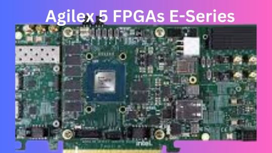
Intel Agilex 5 FGPA
Agilex 5 E-Series
Altera’s latest mid-range FPGAs, the Agilex 5 FPGAs E-Series, are now supported by the recently released Quartus Prime Software v24.1, which can be downloaded right now. Intel are happy to announce that it is now simpler than ever and completely free of charge to take use of the unmatched capability of Altera’s Agilex 5 FPGAs E-Series with the introduction of the state-of-the-art Quartus Prime Software from Altera.
Intel Agilex 5
Free Licence: Get rid of obstacles. With the help of Quartus Prime Pro Edition Software v24.1, you may use the newest E-Series devices at no cost, enabling you to innovate beyond limits!
Streamlined Design Flow: Use Quartus Prime Software to see the smooth integration of intellectual property (IP)-Centric design flow. Their easily customizable design samples streamline the process of getting started so you can concentrate on what really matters your innovative ideas.
New Embedded Processing Capabilities: Make use of the Simics simulator-supported dual-core ARM Cortex-A76 and dual-core ARM Cortex-A55 of the Agilex 5 SoC FPGA, the industry’s first asymmetric processing complex. Additionally, Agilex 5 FPGAs may be combined with the feature-rich, performance- and space-optimized Nios V soft-processor for smaller embedded FPGA applications. Additionally, they collaborate with a number of partners who provide a top-notch suite of tools to improve your FPGA and embedded development experience, including Arm, Wind River, Siemens, Ashling, MathWorks, and many more.
Comprehensive Intellectual Property (IP) Portfolio: With their tried-and-true IP portfolio for Agilex 5 FPGAs, many of which are free, you may shorten the time it takes to market. Reduce the amount of circuitry used and make design timing closure easier with hard IP solutions for PCI Express, Ethernet, and memory protocols, which also support LPDDR5. With PCS’s Ethernet 10G MAC, you can guarantee deterministic and synchronised communication, enhanced by Time-Sensitive Networking (TSN) features.
This version includes the Video and Vision Processing (VVP) portfolio IP for Agilex 5 FPGAs, which enables the entire portfolio of video solutions, as well as additional IPs supporting MIPI D-PHY and MIPI CSI-2. Begin developing your Agilex 5 FPGA designs and rely on additional validated advanced features like JESD204C IP, ORAN IP, LDPC IP, CPRI, and eCPRI among others.
Unprecedented Capabilities: Altera FPGAs may be programmed with cutting-edge capabilities like the following using the Quartus Prime Pro Edition Software v24.1.
Agilex 5 datasheet
Dashboard for Quartus Software Exploration (Preproduction)
With distinct instances of Quartus Prime software, numerous projects running concurrently may be easily coordinated and the compilation and timing results can be seen.
Fresh Features for Compilation: Generation flow of precompiled components (PCCs)Utilising the new precompiled component (PCC) generation flow during compilation, shorten the time it takes to compile synthesis.Start the Simulator using the Quartus Prime GUI.Effortlessly start simulations straight from the Quartus Prime GUI by using the handy “Tools ➤ Run Simulation” menu item. Remove the need for extra procedures to streamline your workflow and save time.
Features and Improvements of Synthesis
Use the RTL Linter Tool to convert older RTL files to Verilog/VHDL standards with ease, optimise RAM inference for better speed and resource use, and reduce warnings in error-free RTL modules to increase readability while developing.
Improved Timing Indicator
Gain more flexibility in timing analysis and SDC scripting with new scripting options; guarantee design integrity with sign-off capabilities for particular combinational loops; and learn more about timing characteristics with enhanced Chip Planner visualisation of asynchronous clock domain crossings (CDCs).
Innovations in Advanced Link Analysers
Link Builder: Use the brand-new Link Builder tool to quickly and easily build high-speed serial connections. Streamline the connection creation procedure by automatically generating schematics and importing channels and devices.
High DPI Monitor Assistance: Benefit from improved readability and display quality thanks to GUI scaling for high DPI displays and automated DPI recognition. Enjoy enhanced usability and user experience.
Enhanced Data Viewer: With improvements to the Data Viewer, analyse forward error correction (FEC) code word faults more effectively. Error outcomes may be easily interpreted and analysed for more efficient error correction techniques.
Enhancements to Simulation Time:
Easy-to-use UI for automated import of devices and channels and schematics. Agilex 7 IP offers faster simulation times with the updated Q run and FEC models.
Qualities:
R-Tile: Transaction Layer (TL) multi-channel DMA IP (AXI) up to Gen5 x16 For flexibility in incorporating third-party PCIe Switch IP, use the bypass mode. A new design example for Gen5 x4 endpoint configuration is also provided.
F-Tile: Utilising FastSIM to reduce simulation time in PIPE mode and providing Ubuntu driver support for all sample designs.increased compatibility for up to 64 embedded endpoints.For greater coverage, the Debug Tool Kit (DTK) was added to the switch IP.
Become a Part of the Community: Hua Xue, VP & GM Software Engineering, remarked, “Intel’re excited to offer Quartus Prime Software v24.1, a crucial milestone in FPGA design.”
“Now, engineers everywhere can easily access the unmatched potential of Agilex 5 FPGAs E-Series.” Quartus’s simplified design process and these cutting-edge technologies allow engineers to reach their full potential for innovation. With their state-of-the-art processing capabilities, Agilex 5 devices transform embedded FPGA applications. These are enhanced by Quartus’s vast IP portfolio, which includes a variety of solutions like Ethernet, PCI Express, memory protocols like LPDDR5, support for MIPI D-PHY, CSI-2, and a suite of video solutions, among many other IPs.
The Quartus Exploration Dashboard offers a user-friendly interface and optimization recommendations, which further improve the design exploration process. Intel’re pushing both the simplicity of use and the fast compiler technologies with Quartus v24.1’s open access to E-Series FPGAs and a simplified design pipeline to enable engineers and innovators to unleash their creativity like never before.”
Intel Agilex 5 price
Normally marketed to corporations and incorporated into bigger systems, the Intel Agilex 5 FPGAs do not have a set pricing that is made accessible to the general public. A number of variables affect the pricing, including:
Model specifics: The Agilex 5 family has two distinct series (D and E) with differing logic cell characteristics and capacities. Models with additional features will cost more.
Volume: If you buy in large quantities, you may be able to negotiate a lower price with distributors or directly with Intel.
Distributor: Price structures may vary significantly throughout distributors.
Read more on Govindhtech.com
#Agilex#intelagilex#agilex5#intelagilex5#govindhtech#FPGA#news#technews#technology#technologynews#TechnologyTrends Intel
0 notes
Text
VHDL Assignment #1: Getting Started with Quartus CAD Software
Instructions
2 Introduction
In this assignment, you will learn how to use Intel Quartus II FPGA design software, how to set up a project, and the basics of writing VHDL code by following a step-by-step tutorial.
3 Learning Outcomes
After completing this lab you should know how to:
Run the Intel Quartus software
Create the framework for a new project
Create a new VHDL file
4 Run Intel…

View On WordPress
0 notes
Link
Digital Design: With an Introduction to the Verilog HDL, VHDL, and SystemVerilog 6th Edition, ISBN-13: 978-0134549897 [PDF eBook eTextbook] Publisher: Pearson; 6th edition (March 7, 2017) Language: English 720 pages ISBN-10: 9780134549897 ISBN-13: 978-0134549897 The speed, density, and complexity of today’s digital devices are made possible by advances in physical processing technology and digital design methodology. Aside from semiconductor technology, the design of leading-edge devices depends critically on hardware description languages (HDLs) and synthesis tools. Three public-domain languages, Verilog, VHDL, and SystemVerilog, all play a role in design flows for today’s digital devices. HDLs, together with fundamental knowledge of digital logic circuits, provide an entry point to the world of digital design for students majoring in computer science, computer engineering, and electrical engineering. In the not-too-distant past, it would be unthinkable for an electrical engineering student to graduate without having used an oscilloscope. Today, the needs of industry demand that undergraduate students become familiar with the use of at least one hardware description language. Their use of an HDL as a student will better prepare them to be productive members of a design team after they graduate. Given the presence of three HDLs in the design arena, we have expanded our presentation of HDLs in Digital Design to treat Verilog and VHDL, and to provide an introduction to SystemVerilog. Our intent is not to require students to learn three, or even two, languages, but to provide the instructor with a choice between Verilog and VHDL while teaching a systematic methodology for design, regardless of the language, and an optional introduction to SystemVerilog. Certainly, Verilog and VHDL are widely used and taught, dominate the design space, and have common underlying concepts supporting combinational and sequential logic design, and both are essential to the synthesis of high-density integrated circuits. Our text offers parallel tracks of presentation of both languages, but allows concentration on a single language. The level of treatment of Verilog and VHDL is essentially equal, without emphasizing one language over the other. A language-neutral presentation of digital design is a – common thread through the treatment of both languages. A large set of problems, which are stated in language-neutral terms, at the end of each chapter can be worked with either Verilog or VHDL. The emphasis in our presentation is on digital design, with HDLs in a supporting role. Consequently, we present only those details of Verilog, VHDL, and SystemVerilog that are needed to support our treatment of an introduction to digital design. Moreover, although we present examples using each language, we identify and segregate the treatment of topics and examples so that the instructor can choose a path of presentation for a single language—either Verilog or VHDL. Naturally, a path that emphasizes Verilog can conclude with SystemVerilog, but it can be skipped without compromising the objectives. The introduction to SystemVerilog is selective—we present only topics and examples that are extensions of Verilog, and well within the scope of an introductory treatment. To be clear, we are not advocating simultaneous presentation of the languages. The instructor can choose either Verilog/SystemVerilog or VHDL as the core language supporting an introductory course in digital design. Regardless of the language, our focus is on digital design. The language-based examples throughout the book are not just about the details of an HDL. We emphasize and demonstrate the modeling and verification of digital circuits having specified behavior. Neither Verilog or VHDL are covered in their entirety. Some details of the languages will be left to the reader’s continuing education and use of web resources. Regardless of language, our examples introduce a design methodology based on the concept of computer-aided modeling of digital systems by means of a mainstream, IEEE-standardized, hardware description language. This revision of Digital Design begins each chapter with a statement of its objectives. Problems at the end of each chapter are combined with inchapter examples, and with in-chapter Practice Exercises. Together, these encounters with the subject matter bring the student closer to achieving the stated objectives and becoming skilled in digital design. Answers are given to selected problems at the end of each chapter. A Solution Manual gives detailed solutions to all of the problems at the end of the chapters. The level of detail of the solutions is such that an instructor can use individual problems to support classroom instruction. Table of Contents: Preface 1 Digital Systems and Binary Numbers 1.1 Digital Systems 1.2 Binary Numbers 1.3 NumberBase Conversions 1.4 Octal and Hexadecimal Numbers 1.5 Complements of Numbers 1.6 Signed Binary Numbers 1.7 Binary Codes 1.8 Binary Storage and Registers 1.9 Binary Logic 2 Boolean Algebra and Logic Gates 2.1 Introduction 2.2 Basic Definitions 2.3 Axiomatic Definition of Boolean Algebra 2.4 Basic Theorems and Properties of Boolean Algebra 2.5 Boolean Functions 2.6 Canonical and Standard Forms 2.7 Other Logic Operations 2.8 Digital Logic Gates 2.9 Integrated Circuits 3 GateLevel Minimization 3.1 Introduction 3.2 The Map Method 3.3 FourVariable K-Map 3.4 ProductofSums Simplification 3.5 Don’tCare Conditions 3.6 NAND and NOR Implementation 3.7 Other TwoLevel Implementations 3.8 ExclusiveOR Function 3.9 Hardware Description Languages (HDLs) 4 Combinational Logic 4.1 Introduction 4.2 Combinational Circuits 4.3 Analysis of Combinational Circuits 4.4 Design Procedure 4.5 Binary Adder—Subtractor 4.6 Decimal Adder 4.7 Binary Multiplier 4.8 Magnitude Comparator 4.9 Decoders 4.10 Encoders 4.11 Multiplexers 4.12 HDL Models of Combinational Circuits 5 Synchronous Sequential Logic 5.1 Introduction 5.2 Sequential Circuits 5.3 Storage Elements: Latches 5.4 Storage Elements: FlipFlops 5.5 Analysis of Clocked Sequential Circuits 5.6 Synthesizable HDL Models of Sequential Circuits 5.7 State Reduction and Assignment 5.8 Design Procedure 6 Registers and Counters 6.1 Registers 6.2 Shift Registers 6.3 Ripple Counters 6.4 Synchronous Counters 6.5 Other Counters 6.6 HDL Models of Registers and Counters 7 Memory and Programmable Logic 7.1 Introduction 7.2 RandomAccess Memory 7.3 Memory Decoding 7.4 Error Detection and Correction 7.5 ReadOnly Memory 7.6 Programmable Logic Array 7.7 Programmable Array Logic 7.8 Sequential Programmable Devices 8 Design at the Register Transfer Level 8.1 Introduction 8.2 Register Transfer Level (RTL) Notation 8.3 RTL descriptions VERILOG (Edge- and Level-Sensitive Behaviors) 8.4 Algorithmic State Machines (ASMs) 8.5 Design Example (ASMD Chart) 8.6 HDL Description of Design Example 8.7 Sequential Binary Multiplier 8.8 Control Logic 8.9 HDL Description of Binary Multiplier 8.10 Design with Multiplexers 8.11 RaceFree Design (Software Race Conditions) 8.12 LatchFree Design (Why Waste Silicon?) 8.13 System Verilog–An Introduction 9 Laboratory Experiments with Standard ICs and FPGAs 9.1 Introduction to Experiments 9.2 Experiment 1: Binary and Decimal Numbers 9.3 Experiment 2: Digital Logic Gates 9.4 Experiment 3: Simplification of Boolean Functions 9.5 Experiment 4: Combinational Circuits 9.6 Experiment 5: Code Converters 9.7 Experiment 6: Design with Multiplexers 9.8 Experiment 7: Adders and Subtractors 9.9 Experiment 8: FlipFlops 9.10 Experiment 9: Sequential Circuits 9.11 Experiment 10: Counters 9.12 Experiment 11: Shift Registers 9.13 Experiment 12: Serial Addition 9.14 Experiment 13: Memory Unit 9.15 Experiment 14: Lamp Handball 9.16 Experiment 15: ClockPulse Generator 9.17 Experiment 16: Parallel Adder and Accumulator 9.18 Experiment 17: Binary Multiplier 9.19 HDL Simulation Experiments and Rapid Prototyping with FPGAs 10 Standard Graphic Symbols 10.1 RectangularShape Symbols 10.2 Qualifying Symbols 10.3 Dependency Notation 10.4 Symbols for Combinational Elements 10.5 Symbols for FlipFlops 10.6 Symbols for Registers 10.7 Symbols for Counters 10.8 Symbol for RAM Appendix Answers to Selected Problems Index M. Morris Mano is an Emeritus Professor of Computer Engineering at the California State University, Los Angeles. His notable works include the Mano Machine, i.e. a theoretical computer that contains a central processing unit, random access memory, and an input-output bus. M. Morris Mano has authored numerous books in the area of digital circuits that are known for teaching the basic concepts of digital logic circuits in a clear, accessible manner. His books for the introductory digital design course, Logic and Computer Design Fundamentals and Digital Design, continue to be two of the most widely used texts around the world. Michael Ciletti is an Emeritus Professor of Electrical and Computer Engineering at the University of Colorado, Colorado Springs. An early advocate of including HDL-based design methodology in the curriculum, he pioneered and developed the offering of several courses using Verilog, VHDL, FPGAs and standard cell based hardware implementations for design, testing, and synthesis of VLSI devices. His consulting work has ranged from processor design to providing expert witness testimony in cases involving HDLs. He has developed and presented courses for industry in The United States, Asia, and Europe. His widely-adopted textbooks have promoted the use of the now-standard Verilog HDL and encouraged adoption of HDL-based design practice in logic design and computer science curricula. Ciletti resides in Colorado Springs, CO, where he pursues a strong interest in landscape photography. What makes us different? • Instant Download • Always Competitive Pricing • 100% Privacy • FREE Sample Available • 24-7 LIVE Customer Support
0 notes
Text
An Introduction to SystemVerilog: Overview and Benefits
Are you looking to get up to speed with the basics of SystemVerilog? This introduction will provide a comprehensive overview of SystemVerilog and all its benefits. SystemVerilog is an incredibly powerful programming language and hardware description language (HDL) used for the verification, design, synthesis, emulation, and prototyping of digital circuits.
The language enables users to efficiently create intricate designs that can be tested quickly and accurately for verification purposes, as well as optimized for cost reduction when transferred into silicon.
Regardless of your previous experience level or coding expertise, this guide provides all the essentials needed to understand why so many people are drawn towards using SystemVerilog in their projects.
What is SystemVerilog?
SystemVerilog is an extension of Verilog, which was developed by Accellera to enhance the design, verification, and synthesis of digital circuits and systems. This language provides object-oriented programming features, constrained random testing, assertions, and coverage analysis. It has become a popular language for both design and verification of digital systems, due to its flexibility and functionality.
Evolution of Verilog to SystemVerilog
Verilog was enhanced to SystemVerilog to address the growing complexity of digital circuits and systems. SystemVerilog added features such as object-oriented programming, constrained random testing, assertions, and coverage analysis to improve design verification, modeling, and synthesis.
Features and capabilities of SystemVerilog
Some of the notable features and capabilities of SystemVerilog include:
Object-oriented programming (OOP) features, such as classes, objects, and inheritance, enable modular and reusable design structures.
Constrained random testing (CRT) allows designers to create random input stimulus while constraining the values to ensure proper functionality and performance.
Assertions and coverage analysis enable designers to check the correctness of their designs and ensure that they meet the desired functional and performance requirements.
Design hierarchy and interface modeling enable designers to organize and manage complex designs with multiple modules and interfaces.
Design reuse and system-on-chip (SoC) design capabilities facilitate the creation of complex designs with pre-designed components and IP blocks.
SystemVerilog also includes features for low-power design, testbench automation, and FPGA synthesis.
Advantages of SystemVerilog
Here are some advantages of SystemVerilog:
SystemVerilog code is more concise and requires fewer lines of code compared to Verilog, which can save time and reduce errors.SystemVerilog includes structures and enumerated types that provide a more scalable and efficient way to design and manage complex digital systems. Interfaces in SystemVerilog provide a higher level of abstraction and enable faster design iterations and easier reuse of IP blocks.SystemVerilog is widely supported in electronic design automation (EDA) tools, including Vivado synthesis, which makes it easy to synthesize and implement designs on FPGAs
SystemVerilog vs. Verilog
Verilog is a Hardware Description Language (HDL) used for modeling and structuring electronic systems, while SystemVerilog combines HDL and Hardware Verification Language (HVL) to facilitate modeling, designing, simulating, testing, and implementing electrical systems.
In Verilog, module-level testing is used for the testbench, while SystemVerilog utilizes class-level test benches for more advanced and efficient testing. While Verilog uses C and Fortran programming languages, SystemVerilog is a programming language that combines Verilog, VHDL, and C++. Verilog supports the datatypes Wire and Reg, whereas SystemVerilog includes enum, union, struct, string, and class datatypes, enabling more versatile modeling and verification capabilities.
In addition to the differences mentioned earlier, Verilog and SystemVerilog also differ in terms of programming paradigms and procedural blocks.
Verilog supports the structured programming paradigm, whereas SystemVerilog supports both structured and object-oriented programming paradigms, enabling more advanced and modular designs.
In Verilog, there is a single always block to implement both combinational and sequential logic. However, SystemVerilog has three procedural blocks, namely always_comb, always_ff, and always_latch, that provide more precise control over logic implementation.
Verilog is based on a hierarchical module design, while SystemVerilog is based on classes that provide more sophisticated design and verification capabilities.
Conclusion
SystemVerilog is an incredibly powerful and efficient tool for those wishing to develop digital designs quickly and reliably. Its encapsulation of VHDL and Verilog properties in one language makes it a necessary addition to any collection of digital design tools.
The interface options, including the command line, graphical user interface, as well as self-verification facilities will empower users with greater flexibility as well as a sound verification process. With such a comprehensive package, it is no surprise that SystemVerilog has become so popular in the design world.
Get ahead of the game with SystemVerilog today – we at Maven Silicon are here to help you along your learning journey! Whether you’re just starting out or already familiar with SystemVerilog, contact us today to get started on our SystemVerilog tutorial.
With us, by your side, you’ll soon be confident enough to tackle more complex projects with ease. Don't wait - take the first step now and explore what SystemVerilog can do for you!
0 notes
Text
VHDL Assignment #6: Storage Elements, Sequential Circuits, and Finite State Machines in VHDL
2 Learning Outcomes
After completing this assignment you should know how to:
Describe sequential elements in VHDL
Design a clock divider circuit
Design a 3-bit counter in VHDL
Perform functional simulation of the counter using ModelSim
Design FSMs in VHDL
Design sequence detector circuits
Test the circuit on the Altera board
3 Introduction
In this VHDL…

View On WordPress
0 notes
Text
Digital Design: With an Introduction to the Verilog HDL, VHDL, and SystemVerilog (6th Edition) eBook
Digital Design: With an Introduction to the Verilog HDL, VHDL, and SystemVerilog (6th Edition) eBook PDF
A modern update to a classic, authoritative textbook, Digital Design, 6th Edition, PDF, teaches the fundamental concepts of digital design in a clear, accessible manner. The textbook presents the basic tools for the design of digital circuits and provides procedures suitable for a variety of…
View On WordPress
0 notes
Text
youtube
EDA Playground Secrets Revealed: Learn VHDL & Verilog in Minutes [Step-by-Step Tutorial]
Here's what you'll find in this video:
* A clear and concise introduction to VHDL and Verilog.
* A detailed walkthrough of the EDA Playground interface.
* Step-by-step instructions for writing, simulating, and debugging your code.
* Real-world examples and practical tips to help you learn faster.
* Don't miss out! Subscribe to our channel for more awesome digital design tutorials and content.
Subscribe to "Learn And Grow Community"
YouTube : https://www.youtube.com/@LearnAndGrowCommunity
LinkedIn Group : linkedin.com/company/LearnAndGrowCommunity
Blog : https://LearnAndGrowCommunity.blogspot.com/
Facebook : https://www.facebook.com/JoinLearnAndGrowCommunity/
Twitter Handle : https://twitter.com/LNG_Community
DailyMotion : https://www.dailymotion.com/LearnAndGrowCommunity
Instagram Handle : https://www.instagram.com/LearnAndGrowCommunity/
Follow #LearnAndGrowCommunity
#EDAPlayGround#VHDL#VerilogHDL#EDATutorial#ElectronicDesignAutomation#DigitalCircuitDesign#CodeSharing#EDAPlatform#VHDLSimulation#HDLSimulation#FPGA#Simulationtool#learnandgrow#Learnandgrowcommunity#vhdltutorial#vhdlprogramming#freetools#simulationsoftware#beginnersguide#stepbystepguide#tutorial#Youtube
1 note
·
View note
Text
Digital Design: With an Introduction to the Verilog HDL, VHDL, and SystemVerilog (6th Edition) eBook
Digital Design: With an Introduction to the Verilog HDL, VHDL, and SystemVerilog (6th Edition) eBook
Digital Design: With an Introduction to the Verilog HDL, VHDL, and SystemVerilog (6th Edition) eBook PDF
A modern update to a classic, authoritative textbook, Digital Design, 6th Edition, PDF, teaches the fundamental concepts of digital design in a clear, accessible manner. The textbook presents the basic tools for the design of digital circuits and provides procedures suitable for a variety of…
View On WordPress
0 notes
Text
VHDL Assignment #2: Design and Simulation of Digital Circuits
2 Introduction
In this assignment, you will learn how to create a circuit using a schematic diagram in Quartus. You will then simulate the circuit in ModelSim. You will also learn how to use the test bench writer tool in Quartus. Finally, you will learn and practice the use of concurrent statements.
3 Learning Outcomes
After completing this assignment you should know how to:
Create a schematic…

View On WordPress
0 notes
Text
Digital design john f wakerly pdf
DIGITAL DESIGN JOHN F WAKERLY PDF >>Download
vk.cc/c7jKeU
DIGITAL DESIGN JOHN F WAKERLY PDF >> Leia online
bit.do/fSmfG
Blends academic precision and practical experience in an authoritative introduction to basic principles of digital design and practical requirements. Desenvolvimento de circuito digital usando VHDL;. •. Sistema Digital como Unidade de controle e WAKERLY, John F. Digital Design Principles & Practices.13 de mai. de 2021 — Digital Design [ Principles and Practices Fourth Edition * John F. W akerly. DIGITAL DESIGN Principles and Practices Fourth Edition Digital Design - Principles and Practices (4th Edition) [John F. Wakerly].pdf - Free ebook download as PDF File (.pdf) or read book online for free. "Digital Design: Principles and Practices" por John F. Wakerly, 4th Edition, 2005. Wikipedia: “digital circuit”. Outros livros. Disponíveis na Biblioteca! DD Project PPT (1).pdf Traffic Light Controller.pdf Ciletti: Digital Design with an Introduction to the Verilog HDL Wakerly, John F:"Digital Design 15 de jul. de 2021 — Digital Design Principles And Practices - Wakerly · 1.Introduction · 2.Number Systems and Codes · 3.Digital Circuits · 4.Combinational Logic Design
https://www.tumblr.com/lihiharumuk/697856142239547392/myoclonus-causes-pdf995, https://www.tumblr.com/lihiharumuk/697856142239547392/myoclonus-causes-pdf995, https://www.tumblr.com/lihiharumuk/697856142239547392/myoclonus-causes-pdf995, https://www.tumblr.com/lihiharumuk/697856142239547392/myoclonus-causes-pdf995, https://www.tumblr.com/lihiharumuk/697856142239547392/myoclonus-causes-pdf995.
0 notes
Text
Vhdl pdf
VHDL PDF >> DOWNLOAD LINK
vk.cc/c7jKeU
VHDL PDF >> READ ONLINE
bit.do/fSmfG
vhdl openclassroom
vhdl cours et exercices corrigés pdf
registre à décalage vhdl pdfvhdl cours
vhdl process
tp vhdl
vhdl exercices corrigés
vhdl abréviation
VHDL permet de manipuler des objets typés. • un objet est le contenant d'une valeur d'un type donné. • 4 classes d'objets : – CONSTANT : objet possédant une Le placeur/routeur génère une description VHDL interconnectant des composants de la librairie du circuit ciblé dont les modèles de simulation sont conformes à VHDL. 1164. STD LOGIC. Définition du langage : - version 1076-87. - version 1076-93. Package définissant les niveaux logique nécessaire pour la descriptionII) RELATION ENTRE UNE DESCRIPTION VHDL ET LES CIRCUITS LOGIQUES II.1) SCHÉMA FONCTIONNEL D'IMPLANTATION DE DESCRIPTIONS VHDL DANS UN CIRCUIT LOGIQUE. Page 2. VHDL – Logique programmable. Partie 2 – La structure d'un programme VHDL. © D.Giacona. 2/47. 1. Éléments fondamentaux du langage VHDL . Structure d'un programme VHDL library ieee; use ieee.std_logic_1164.all; entity toto is port (. ); end toto; architecture test of toto is begin end test;. Introduction à VHDL eqcomp4. A[3:0]. B[3:0] égal. -- eqcomp4 est un comparateur 4 bits entity eqcomp4 is port (a, b: in bit_vector(3 downto 0);.
https://rekototed.tumblr.com/post/694298150168592384/hapitre-n-4-le-moteur-asynchrone-dinduction, https://nicepewuma.tumblr.com/post/694299365660065792/visseuse-bosch-ixo-mode-d-emploi, https://soxunucob.tumblr.com/post/694299992153899008/sauter-baladi-mode-demploi-lego, https://soxunucob.tumblr.com/post/694299992153899008/sauter-baladi-mode-demploi-lego, https://rekototed.tumblr.com/post/694298150168592384/hapitre-n-4-le-moteur-asynchrone-dinduction.
0 notes
Last Seen Blogs

flametrashiraarchive
Flame Trashira Archive

day6source
you are my day

the-world-of-fallen-angel
my world

gravitycoill
connor

sirtravisjacksonoftexas
Untitled