#2D Drawing to Part Inspection
Text
How I draw: Silver Metallic Buttons for Sims 2 Textures
As we all know, Sims 2 doesn't really appreciate large file sizes/dimensions for it's textures, so sometimes you have work very closely with the individual pixels. Here is how I draw buttons. Video is sped up so don't feel like you need to draw as fast as me!
Side note: this tutorial is created on the basis that you already know how to use the basic functions of Sims BodyShop to extract the texture file. There's plenty of tutorials out there explaining that so please don't ask me to clarify on that part. Anyway, on to the buttons...↓↓↓
What you need:
A PC
Digital Drawing app (like Photoshop, Krita etc)
A Graphics Tablet with pen - you could try this with a mouse but I wouldn't recommend!
And obviously Sims 2/Sims 2 BodyShop
First off, create a new layer - we don't want this button permanently stuck to our base texture. Then I get a standard hard edge brush (I use Krita as my drawing software, so just use whatever hard brush is available in your preferred software/app). Because I'm making relatively small buttons, I make my brush 7.09px in size. Select a mid to light grey colour as the base. Make a single circle.
Then decrease the brush size to be nice and small. As a comparison to my 7.09px circle, I decrease to 0.01px for this next step. Choose a slightly darker grey colour and lightly sketch in a 'semi-circular line' about 3/4 of the way around just in from the edge of the circle. By lightly sketching - and not pressing down hard, you'll get varying tones on each pixel to represent different reflections on the 'metal'.
Next choose a darker grey again, and lightly sketch around the similar area as the last colour, but don't be too fussy on hitting the same pixels - we want varying tonal values for our shadows.
Then choose white and lightly sketch the 'catch light' part of the button. This doesn't need to be right in the centre, in fact it's better if it's off to the side, or towards the top more. We're not always facing directly towards a light source so this creates a more realistic lighting effect. You'll see me select the same mid to light base grey I used just to lightly dust over the edges of the white area to soften it a tiny bit (only do this if your white edge is a little to crisp).
After that I go back and forth between a few different tones of grey to lightly sketch over the parts we haven't really drawn on yet. This just helps create some gradual shading that enhances the 'roundness' of our very flat, very 2D button texture.
Once you're happy with the shadowing (remember it looks somewhat janky this close up, but you can always zoom out to see if the button looks more smooth when further away), you can then make another layer, and drag it below your newly made button layer in the layer menu. Select a soft edge brush and increase the size to slightly wider than your buttons overall size (I chose 9.14px compared to my 7.09px button)
Choose black from the colour wheel/palette and lightly build up the shadow underneath the button, gradually increasing size and opacity until desired tone. If the colour of the 'garment' in this texture is light then keep the shadow to a minimum, if it's dark then the shadow needs to be deep enough to show up.
Zoom out and inspect how this button looks further out. If you're satisfied, then merge the button and shadow layers together, copy/paste it as many times as needed for the garment you're texturing and Voila! You made buttons for a Sims 2 Texture!!
Feel free to ask any questions below - I'm definitely no professional, especially in creating tutorials so I'm more than happy to clarify if something didn't make sense.

#sims tutorial#digital drawing#retexture#drawing tutorial#ts2#the sims 2#digital art tips#lraerosesims#lraerosesims-tutorials
87 notes
·
View notes
Text
It's the Twins Birthday (or all their birthday I don't know), and they're having a blast with the party, games, food, dancing, and of course the presents!
Mikey approaches Donnie with a tablet in hand. "I want to give one of my gifts next!~"
Donnie with a small smile and a raised eyebrow questioned, "What gift do you have on your tablet Michael?"
Mikey turns on the tablet, and shows multiple sets of drawings on the screen, "Well since you wanted to restart your YouTube channel anew, I looked into some ways you could do things, and figured why not make some VTuber models of all of us! Both 2d, and 3d of course."
On closer inspection the drawings were infact reference sheets for each brother, 3D models of each brother, and 2D models separated into parts for rigging.
Donnies eyes widen with amazement at the reference sheets. Leo and Raph lean in behind Donnie to see the tablet.
"Raph would like to know what a Vee Tuber is." Raph says with confusion.
Leo takes over for the explanation, "A VTuber is a Youtuber/Streamer/content creator that uses an animated model instead of showing themself. Usually as a separate persona with a Backstory attached. They got very popular in the last few years."
"Indeed, Nardo is correct. And I love it Michael! I can't wait to start rigging these, and testing them out! Excitement Overload~~!" Donnie starts stimming a lot.
"And I will help you with backgrounds, clothes, and other art related things." Mikey chirps.
"Anywizzle~ Why did you make models of all of us if this was mainly for Dontron? Unless~" Leo starts to say with excitement.
"I want us to all be apart of this VTuber streaming thing, even if we can't all do much because of our day jobs." Mikey explains.
They all agree, and start putting together a basic plan that they will work out more another day, and not during the party.
They of course told the rest of their family and friends about their plans, and the only ones not really getting it were Splinter and Draxum.
~~~~~~~~~~~~~~~~~~
Donnie and Mikey work together to set up the various art assets, backgrounds, and the starts of their models 'outfit closets' and setting up how the scenes would work for streaming. On top of the rigging and some small tests of the tracking.
It took them a bit of time, and remembering to create a new channel for their new VTuber project.
Donnie was setting up a private test stream to test out his custom full body tracking rig, and hoped things went over well for their eventual VTuber debut...
Right~~
--------------------
Masterpost
A little bit of lore for my VTuber au.
#VTurtles!#vtuber au#rottmnt au#tmnt au#rottmnt donatello#rottmnt donnie#rottmnt michelangelo#rottmnt mikey#rottmnt leonardo#rottmnt leo#rottmnt raph#rise donatello#rise donnie#rise michelangelo#rise mikey#rise leonardo#rise leo#rise raph#rottmnt fanfiction#tmnt fanfiction#rottmnt#rise of the teenage mutant ninja turtles#tmnt 2018#rise tmnt#rise of the tmnt#teenage mutant ninja turtles#tmnt#rottmnt raphael#rise raphael
20 notes
·
View notes
Text
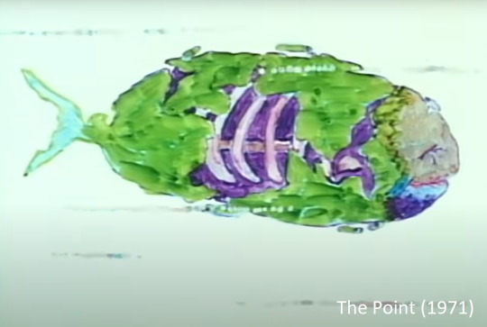
The Point (1971)
Harry Nilsson’s 1971 animated TV special “The Point” is an unassuming thing- a cartoon which upon closer inspection is one of the most indicative examples of the Rollerwave aesthetic possible.
It resembles a segment from an early episode of Sesame Street or Schoolhouse Rock, which makes sense when you consider that it was animated by Fred Wolf, creator of the famous Tootsie Pop commercial with the owl. His sensibilities in bringing Nilsson’s album to life are fitting in that they convey a surreal, extremely colorful world with no fixed rules.
The story is rare in that it will appeal to both children and adults, far more than any segment from Schoolhouse Rock or Sesame Street. This is mainly due to the film’s theme of deliberate absurdity- that is, it is not designed to educate as much as it is to make the viewer think. These are two very different approaches. The Point is philosophical rather than methodical, it does not hammer any one particular idea into the audience’s head, and at times it is intentionally confusing, which is something you would not expect from a cartoon of this period.
The work most readily comparable to The Point is, of course, Norton Juster’s 1961 masterpiece The Phantom Tollbooth, in that, like The Point, its settings and characters are entirely allegorical. This method of storytelling seems especially popular around the 1960s and 1970s, rejecting the straightforward methods of the 1950s. The Phantom Tollbooth also contains vivid illustrations, particularly similar in their cross-hatching, messy ink style. Fans of Jules Feiffer will, I think, appreciate the style of Fred Wolf to an equal extent.
Some parts of this film draw attention to just how much we’ve changed as a society since the 1970s, and how much we’ve altered what is considered “acceptable” for children. During one abstract musical number, for instance, a dead whale is depicted, slowly rotting away, frame by frame. A modern viewer would see morbid imagery like this as only fitting in a Don’t Hug Me I’m Scared-type parody. In the 1970s, however, this was seen as not only acceptable to show children, but important, in that it adequately conveys the grim yet natural reality of death, and the cyclical system of nutrients in the ocean’s ecosystem. Other examples of children’s media being deliberately censored with the misconception that it would be deemed offensive include the infamous lost Sesame Street segment, “Cracks,” which was obfuscated during the 1980s cocaine epidemic despite having nothing to do with cocaine.
The Point, as I mentioned, is a philosophical fable with the key theme of societal acceptance and dehumanization. On the other hand, its title serves as wordplay, in that it asks what it means for something to have a point. By the end, the viewer is left asking themselves whether the cartoon had any sort of point. This element is aided by dialogue which is obtuse by design, and a meandering plot which attempts to defy the well-documented “Hero’s Journey” structure in favor of an episodic series.
The frame surrounding the tale is equally abstract, featuring a father who reads a bedtime story to his son, all the while sarcastically commenting about how “kids these days just want to watch TV” and his son views the story, presumably as the film itself, on the TV next to his bed. The father was voiced by four people across The Point’s broadcast history, two of which were Dustin Hoffman and Ringo Starr, and watching each version provides a somewhat different experience, given the varying inflections of the narrators.
This may very well be the ultimate animated Rollerwave film, ideal for anyone wanting to know more about the visually artistic side of the aesthetic, departed from live-action. It is inspiring for anyone looking to enter the realm of 2D animation, with its detailed landscapes and vibrant color. One can only long for this period, when animating a full album and bringing an hour-long narrative to life using nothing but pens, paper, and watercolor paint was considered routine. The result is well worth your while.
4 notes
·
View notes
Text
Supplier of Industrial Fittings in Maharashtra
Meghmani Metal Industries is one of the leading Manufacturer and Supplier of Industrial Fittings in Maharashtra, India.
Meghmani Metal Industries was established in 2011, We are committed to delivering top-notch products to the metal industry, prioritizing customer satisfaction, and environmental stewardship.
We offer a wide range of stainless steel products including plates, coils, bars, wires, pipes, tubes, industrial flanges, valves, fittings, fasteners, SS channels, and flats.
Industrial Fittings are devices connecting parts of machinery, designed to endure harsh conditions. They're vital in manufacturing, construction, and utilities for tasks like piping and plumbing.
Our testing and inspection services for industrial fittings include mechanical testing, chemical analysis, corrosion testing, microstructure examination, hydro testing, surface finish analysis, and non-destructive testing using various techniques and equipment.
Technical Specifications:
Size: 1/8” NB TO 48” NB (Seamless & 100% X-Ray Welded, Fabricated).
Thickness: SCH: 5s, 10s, 40s, 80s, 10, 20, 40, STD, 60, 80, XS, 100, 120, 140, 160, XXS, Custom Thickness.
Dimension: B16.5, BS 4504, EN-1092.
Specialization: Long Bend with Radius – R = 1D, 1.5D, 2D, 3D, 5D, 6D, 8D, 10D or custom Pigabble Bend & As per your drawing.
Value Added Services: Polish (Electro & Commercial), Heat Treatment Annealed & Pickled, Sand Blasting, Machining, etc.
Applications :
Waste treatment facilities
Chemical processing
Breweries
Petrochemical facilities
Cryogenic plants
Nuclear power plants
Meghmani Metal Industries is one of the leading Manufacturer and Supplier of Industrial Fittings in Maharashtra and places like Ahmednagar, Akola, Amravati, Aurangabad, Bhandara, Jalgaon, Kalyan, Karli, Kolhapur, Mumbai, Nagpur, Nanded, Nashik, Osmanabad, Pandharpur, Parbhani, Pune, Ratnagiri, Sangli, Satara, Sevagram, Solapur, Thane.
If you have any queries or would like more information, please get in touch with us.
0 notes
Text
Exploring the Integration of Virtual Reality and Augmented Reality in Architecture
In recent years, technological advancements have revolutionized various industries and architecture has been no exception. With the emergence of virtual reality (VR) and augmented reality (AR) technologies, architects and designers now have powerful tools at their disposal to enhance their creative processes, streamline workflows, and improve client engagement. The integration of VR and AR in the architecture industry holds immense potential, offering benefits ranging from immersive design experiences to more efficient project communication and collaboration. Let's delve into the impact and possibilities of incorporating VR and AR into architectural practices.
Enhancing Design Visualization
One of the primary advantages of VR and AR in architecture lies in their ability to provide immersive design visualization experiences. Traditionally, architects relied on 2D drawings, blueprints, and physical models to convey their design concepts to clients and stakeholders. However, these methods often need to fully communicate the spatial qualities and aesthetic nuances of a design.
By leveraging VR technology, architects can create virtual environments that allow clients to explore and experience proposed designs in a highly immersive manner. Clients can virtually walk through buildings, inspect various design elements, and get a realistic sense of scale and proportion. This level of immersion not only helps clients better understand the architect's vision but also enables them to provide more informed feedback, leading to more successful design outcomes.
Similarly, AR enables architects to overlay digital models onto real-world environments, offering a unique perspective on how proposed designs will interact with their surroundings. With AR-enabled devices such as smartphones or tablets, stakeholders can visualize buildings and structures within their actual contexts, helping them make informed decisions about design interventions and site planning.
Streamlining Collaborative Workflows
Collaboration is an integral part of the architectural design process, involving architects, engineers, contractors, and clients working together to bring a project to fruition. However, coordinating and communicating design ideas across diverse teams can be challenging, especially when dealing with complex spatial concepts and technical details.
VR and AR technologies facilitate better collaboration by providing shared virtual spaces where stakeholders can interact with and contribute to the design in real time. Virtual meetings conducted in VR environments allow team members from different locations to come together virtually, review designs, and discuss project details as if they were in the same room. This level of collaboration fosters greater synergy among team members, reduces misunderstandings, and accelerates decision-making processes.
Furthermore, AR-enabled collaboration tools enable on-site workers to overlay digital annotations and instructions and build information models onto physical spaces, enhancing communication and coordination during the construction phase. This integration of digital information with the physical environment promotes greater efficiency, accuracy, and safety on construction sites.
Improving Client Engagement and Communication
Effective communication is essential for ensuring that architectural projects meet clients' expectations and requirements. However, conveying design concepts and proposed solutions to clients who may need more architectural expertise can be challenging using traditional methods alone.
VR and AR technologies offer architects powerful tools for engaging clients in the design process and facilitating clear communication. Through VR presentations, clients can immerse themselves in virtual environments and provide feedback on design elements in real time. This interactive approach not only enhances client satisfaction but also fosters a deeper understanding of design intent and project objectives.
AR can also be utilized during client presentations to overlay digital models onto physical models or existing spaces, enabling clients to visualize design proposals in context. By superimposing digital renderings onto real-world environments, architects can demonstrate how proposed designs will integrate with existing structures and landscapes, fostering a more informed dialogue with clients.
Overcoming Design Challenges
While the integration of VR and AR in architecture offers numerous benefits, it also presents specific challenges that need to be addressed. One such challenge is the need for specialized hardware and software, which can be costly and require additional training for architectural professionals.
Furthermore, ensuring the accuracy and fidelity of virtual and augmented representations poses technical challenges, mainly when dealing with complex architectural geometries and material textures. Architects must invest in high-quality modeling and rendering tools to create immersive and realistic virtual experiences that accurately reflect their design intentions.
Despite these challenges, the potential of VR and AR to transform the architecture industry is undeniable. By embracing these technologies, architects can unlock new possibilities for design exploration, collaboration, and client engagement, ultimately leading to more innovative and successful architectural projects. As VR and AR continue to evolve, their integration into architectural practices is poised to redefine the way buildings are designed, constructed, and experienced in the years to come.
0 notes
Text
Basic Guide to Autodesk Inventor and How Does It Work?
I am a mechanical engineering and at the time of writing this post I have more than 10+ years of experience in mechanical design during my whole experience if any software I have used a lot is Autodesk Inventor and it is close competitor of SolidWorks in term of feature and in term of price as well. In this article we will learn what is Autodesk Inventor and How Does It Works in term of mechanical design?
Those who are not aware about Autodesk Inventor it is 3D modeling parametric software owned by Autodesk. Apart from 3D modeling it is also used for simulation, visualization and documentation. As Autodesk Inventor is parametric in nature therefore 3D model and their respective 2D drawing are linked to each other which means if an engineer updates 3D model then 2D drawing will be updated automatically. Autodesk Inventor used its own geometric modeling kernel known as ShapeManager. Autodesk Inventor provides ultimate parametric design capabilities with, free-form and rule-based modeling approach. It has many inbuilt tools like sheet metal, frame, tube, cable and harness design, layout, rendering, simulation, machine design and much more. for modeling of different types of part.
Also Read:
- Meaning of PN and DN in Valves
- Select Shaft Diameter with respect to Bearing Number
- Render FreeCAD Part in CADRays
Silent Feature of Autodesk Inventor:
Autodesk Inventor comes with Powerful blend of parametric, direct, freeform and rules-based design capabilities.
Autodesk Inventor have Integrated tools for sheet metal, frame design, tube and pipe, cable & harness, presentations, rendering, simulation, machine design and more.
Autodesk Inventor comes with TrustedDWG compatibility and powerful Model-Based Definition capabilities for embedding manufacturing information directly in the 3D model.
Unlike other CAD 3D modeling tool Parts Are Inventor’s main building blocks. In Autodesk Inventor Part are created by defining feature like extrude, revolve, loft etc. and these feature are based on sketch. Any mistake made in sketch or feature can be edited later due to parametric nature of Autodesk Inventor. In Autodesk Inventor we can easily create assembly by linking the part by adding constraints between surfaces, edges, planes, points, and axes. If system configuration as per version installed on the system Autodesk inventor can handle large type of assemblies.
Also Read:
- Basic Guide to Choosing ISO or ASME Standard for 2D Drawing
- Beginner Guide to Computer Aided Design
- Basic Guide to UC Bearing Number Designation
Autodesk Inventor as good as other 3D modeling software for creating 3D digital prototypes used in product design, visualization and simulation for mechanical design. Its parametric solid modeling techniques to rapidly modify and adapt the shape of part. As far as 3D printing is concerned Autodesk Inventor model can be exported in STL format for 3D printing. Now a day’s people are using 3D printing as lot especially for machine whose spare part company has stopped manufactured. If you have STL file exported from Autodesk Inventor and you are looking for 3D printing software, then I personally recommend you to use Prusa Slicer which is completely free.
Latest version of Autodesk Inventor is of 2024 and with each new version Autodesk adds new feature. In current version an engineer can send model to fusion 360 for design inspection and you can write iLogic code to perform operations such as copying files, defining numbering schemes, and extracting documents in Autodesk Vault.
“Thank you for reading! If you found this article insightful and valuable, consider sharing it with your friends and followers on social media. Your share can help others discover this content too. Let’s spread knowledge together. Your support is greatly appreciated!”
Read the full article
0 notes
Text
3D Scanning, 3D Metrology, 3D LiDAR Scanning Toronto
The scientific examination of a physical object's measurements is known as 3D metrology. In manufacturing, it involves the accurate measurement of fixtures, tools, and machined parts. In its most basic form, 3D metrology involves precisely obtaining an object's geometrical data along the x, y, and z axes. Traditionally, a coordinate measuring machine (CMM), which is usually programmed to choose only a few places on a part's surface and provides text-based outputs, has been used to obtain these measurements. The current method for 3D metrology, however, involves using CAD-based 3D metrology software to 3D scan an object in order to collect millions and thousands of precise points across a part for thorough inspection.
Polyworks Inspector 3D Metrology software is used by V3D Technologies for quality control and dimensional analysis. It provides 3D scan to CAD deviation analysis, an established method for assessing the accuracy and caliber of various physical items. This technique can be applied to both newly made components and old ones to assess wear and deterioration. This method reveals discrepancies between the 3D scan and the CAD model when the surface features and other geometry are not in tolerance. Polyworks Inspector guarantees process dependability for measuring results and reporting by ensuring that all process stages are traceable, based on the parametric principle that underpins all functions.
3D Scanning is the process of tri-dimensional capture of real-world objects or environments so that they can be re-modelled or analyzed in the digital world. This digital model can then be used for various purposes, including 3D printing, reverse engineering, quality inspection, and more. Our cutting-edge technology and experienced team make us the go-to choice for all your 3D scanning needs. We can create an accurate digital model of your physical object, which can be used to create CAD models for engineering and manufacturing purposes. Our metrology grade laser 3D scanning technology allows us to quickly and accurately inspect the quality and dimensions of your products to ensure they meet the required standards.
Professionals in the Architecture, Engineering, and Construction (AEC) sector can expedite the documenting of current conditions by using our 3D LiDAR scanner to scan big, intricate as-built structures. The creation of a digital twin of as-built structures using an accurate 3D point cloud from a LiDAR scanner facilitates the extraction of precise measurements, the creation of a Building Information Model (BIM), the updating of CAD models, and the creation of 2D drawings. With our special 3D Walkthru Virtual Tour, you and your team may cut down on or completely eliminate time-consuming site visits while keeping accurate track of project progress and making educated decisions.
0 notes
Text
How are Precision Turned Components Manufactured?
Precision machined components get their name because they apply precisely and produce the expected results when used in a machine. These components are essential for modern manufacturing because modern precision devices must attain incredibly small tolerances and exact fittings.
The idea of precise machining is not new, but with the development of computers and software, the manufacturing process has added a new degree of accuracy, fit, and tolerance. This category includes all machining operations, including turning, milling, drilling, honing, grinding, and other operations, all of which benefit from CAD and CAM software.
Sketch/drawing
Obtaining the drawings, technical specifications, and parameters for the parts is the first step in making precision turned components. As the design is input into the computer system, all that is required to begin is a sketch with the appropriate markings. Before being submitted for approval, a drawing provided by the customer is revised internally.
CAD
The technical specifications are entered into the computer-aided design software because a sketch or drawing by itself won't enable a precise manufacturing process. As opposed to a 2D depiction, which makes it impossible to see around bends, slits, and difficult-to-reach areas, CAD software enables 3D rendering of the drawing. After the redesigning is finished, the machine parts manufacturer in Texas sends the revised sketch and the 3D design for final approval.
Machining
The customer's consent is required before the machining process may start. Precision machining, sometimes known as CNC machining, is performed differently than on a standard lathe. The machine uses the input data to build precise cuts, drills, holes, bevels, and threads that give the blanks the desired shapes in accordance with customer specifications.
Post-machining
The work is not finished simply by drilling, cutting, or imparting the necessary shapes to blanks. Some of the things that need to be examined during the post-machining process are deburring, inspection, and dimensional integrity. After everything is completed, each part is given a final check to ensure that it complies with the plans before being produced as exact machine parts.
After the process
While the technological requirements for producing precisely machined components are important, it is also important to emphasize the value of a human operator who is familiar with the CNC process and precision machining. Despite the fact that CNC machines can operate independently, it is essential to have a supervisor to make sure that each item conforms to the tolerance parameters specified for that particular part.
Mastering precision
Precision-turned components are vital in modern manufacturing. They are made with meticulous sketches and technical specifications. Transformed into 3D designs via Computer-Aided Design (CAD) software, these blueprints guide the manufacturing process.
Advanced CNC machining techniques, driven by these designs, craft intricate cuts, holes, and threads with utmost accuracy. Post-machining, rigorous inspections using tools like coordinate measuring machines guarantee dimensional integrity and flawless finishes.
Integrating human expertise, technological precision, and stringent quality checks, manufacturers ensure every component meets exact specifications. This synergy between human skill and cutting-edge technology defines the art and science behind precision turned components that shape diverse industries worldwide.
Resource Box
Buy precision machine components from Arek Solutions because they are a reputed precision machining parts manufacturer who meticulously crafts parts to provide you with components with accuracy. You can buy turned parts for any industry from Arek Solutions.
#precision machined components#precision machining parts manufacturer#precision turned components#machine parts manufacturer texas#machining components
0 notes
Text
The Importance of Quality Control in Laser Marking and Custom Metal Fabrication
In today's fast-paced manufacturing industry, laser marking and custom metal fabrication have become essential processes for creating precise and intricate designs. Whether it's for flat parts, surgical instruments, automotive components, or any other metal-based product, quality control plays a pivotal role in ensuring the highest standards are met. Let’s delve into the significance of quality control in laser marking and custom metal fabrication processes, exploring how these techniques are revolutionizing industries in California and beyond.
Fiber Laser Engraving: Recreating Diverse Designs in 2D:Laser marking california, especially fiber laser engraving, has gained immense popularity in recent years due to its ability to recreate the most diverse designs in 2D. By utilizing advanced laser technology, intricate patterns, logos, serial numbers, and other details can be etched onto various metal surfaces with unparalleled precision. However, to ensure consistency and accuracy, quality control measures are imperative throughout the entire laser marking process. Thorough inspections of the laser equipment, regular calibration checks, and adherence to strict quality standards guarantee the desired outcomes are achieved consistently.
Custom Metal Fabrication: Turning Ideas into Reality: Custom metal fabrication california, coupled with specialized design services, enables the transformation of ideas into reality. Through the use of CAD (Computer-Aided Design), Rhino, Corel Draw, and other software, skilled designers can create intricate drawings and projects tailored to the specific requirements of clients. Quality control is integral at every stage of the fabrication process, from material selection and cutting to welding, polishing, and final assembly. By implementing stringent quality control procedures, manufacturers can ensure that each step adheres to the highest standards, resulting in a finished product that meets or exceeds customer expectations.
All in all, the importance of quality control in laser marking and custom metal fabrication cannot be overstated. By investing in advanced laser technology and implementing comprehensive quality control protocols, the industry can continue to evolve, offering innovative solutions and driving progress in various sectors.
1 note
·
View note
Text
GD&T Symbols: A Complete Guide To GD&T Basic
GD&T Symbols: A Complete Guide To GD&T Basic
In manufacturing, quality is important, prices must be kept under control. It is a tendency to design programs to reduce waste and make efficient use of available resources.Get more news about gd&t symbols,you can vist our website!
There has never been a time when precision and basic dimensions in component design and manufacturing methods were more important than it is today. It is critical that the design intent and performance characteristics of the part features are clearly communicated between the design engineers, mechanical engineers, and the manufacturing plant, which can be accomplished through geometric dimensioning and tolerancing.
The GD&T approach is presently in use in many sectors, including automated equipment, mechanical engineering, aviation, and others. In this article, we will get an overview of GD&T in the manufacturing industry.
What Is Geometric Dimensioning And Tolerancing (GD&T)?
Geometric Dimensioning and Tolerancing (GD&T) or geometric tolerancing is a set of systems that describes a part’s nominal geometry as well as the geometric tolerance for variation that may be allowed. By using the correct tools, a design engineer can clearly characterize a feature’s placement on the component and get the geometric characteristics as well as its size, shape, and orientation. GD&T is designed to be used in conjunction with the basic dimensions and coordinate dimensioning system, rather than as a substitute for it.
The terms “geometrical product specifications” and “geometric dimensioning and tolerancing” relate to a product’s form, size, and positional relationship, while “tolerance” refers to the permissible error.
Designers and engineers use this international language to precisely describe the dimensions, shape, orientation, and position of feature size on their drawings. The GD&T technique takes into account the function of a component as well as how that part interacts with other parts. It is necessary to have an in-depth knowledge of the function of the component inside an assembly in order to use GD&T effectively.
GD&T is an important tool that helps engineers communicate the tolerances of a design. It is a precise language that allows for consistent interpretation of a drawing. GD&T also allows for manufacturability and inspection of a product. When used correctly, it can help reduce scrap, rework, and delays in production. The following are some of the importance of GD&T.
Ensure the use of tolerance required
A robust GD&T process ensures precise fulfillment of all basic dimensions and geometric tolerances parameters by clearly expressing all design requirements at the beginning of the process.Provide assistance with digital design methods
Clear, simple GD&T data is easily convertible to digital design systems, including the practice commonly used 2D and 3D CAD software.
Deliver uniformity as well as convenience
Due to the fact that it is one constant language, geometric design and technology (GD&T) in engineering drawings eliminates guessing and interpretation while maintaining consistent geometries across the design and production processes. Theoretically, all dimensions should not be subject to more than one interpretation.
0 notes
Text
Can Coordination Drawings Help in Creating 2D and 3D Views of a Building?

Building construction is such a job that requires lots of planning and preparation. A single mistake will result in a heart rendering loss. Also, it may result in collapsing of the building and take a huge toll on lives.
That is why, before starting with the actual work; contractors prefer going through some demonstrations. Though there are innumerable numbers of ways to get a view of the going-to-be building, none is as effective as coordination drawings.
These drawings help in coming up with 2D and 3D views that serve as the highest level of convenience for the engineers.
Also Read : Why Are Plumbing Shop Drawings Important for Effective Plumbing System Installation?
What do 2D and 3D Views Reveal about a Building?
As clear by the names, 2D and 3D views of a building specify the entire dimensions that are involved in a building. 2D comprises two dimensions that include length and width. Whereas, 3D shape will help in coming out with additional detail which is none other than height.
The HVAC shop drawings created carefully will provide both these views of a building for convenience. It will provide a crystal clear concept of every corner ranging from plumbing to fitting electrical parts.
Some corners of building becomes difficult to make out with the help of 2D views. Then, 3D views serve to be of great help that helps in carrying out a detailed inspection of that specific portion.
Also Read : A Comparison Between Plumbing And Coordination Drawings
How Coordination Drawings Help in Costly Construction Mistakes?
The coordination drawings are prepared carefully by depicting each and every corner of the building. Both the inner and outer views are brought in front of the architect by maintaining accuracy.
Studying these drawings provides a rough idea of the cost that will incur. It also provides an idea about the total time it will take in completing the construction.
If any types of flaws are found, then immediate action will be taken. Detailed discussions will take with other engineers to discuss the pros and cons. Based on the inference, it will become easy to halt to the best decision.
In all, the role played by HVAC coordination drawings speaks a lot about the building that will be constructed. From plumbing to other matters, everything can be gauged and fixed as needed.
Full Audio: Listen Here
Direction: Click Here
#coordination drawings#plumbingshopdrawings#hvacshopdrawings#duct shop drawings#construction coordination drawings#mep coordination drawings#coordination drawings in construction
0 notes
Text


Independent Excursion: Media Reflection
June 8th - Studio Ghibli Museum
For my media reflection, I decided to go to the studio ghibli museum. This worked perfectly for me because I had just watched most of the films prior to coming on this trip, so I was super excited to find out that there was a museum in Tokyo, and I could do my assignment on it. We are so lucky to have Lauren and Eliza. They worked hard at trying to get tickets for everyone, and figured out the website and what to do when it was not looking good and not letting anyone buy tickets. We all headed over to the museum, and was delightfully greeted by the man and myth himself, Totoro. He was working the ticket booth. We gained access to the museum and they gave us a movie ticket that was a film reel of a scene from one of the movies, but unfortunately we were not able to take pictures inside the museum. The whole place was designed like a wonky house, with spiral staircases, bridges, small rooms with minnie doorways. There were lot of different rooms to inspect. One if the bigger areas looked like it would be the workspace of some of the designers of the franchise. With sketches all over the walls and scattered over desks, newspapers, pens, pencils, feather things, lamps, cigarette butts. It felt real, and was very detailed, I was super impressed. There was another room thaw was a little walk through of miniature replicas of some of the main objects or scenes in some of the earlier films.
My favorite room was an interactive display of how film works and other special effects. There was little gear operated sets that you have to crank the handle to get it to work, there was a motion picture display with a bunch of figures molded to be in different points in time that was spun on a wheel really fast so it looks like it’s actually moving. There were these layered pieces that looked 3d because of 2D drawings layered at different points in a box. There was also a film display that had rolls of film being pulled through a processor I’m assuming, and some where highlighted so you could see that when each square goes by fast enough, it looks like a movie. With all these beautiful pieces, and the light hearted music playing, I started to tear up a little because it was so cute and just made me so happy. We took a little break and ate at the cafe, then went back inside to watch the short film they gave us the ticket for. It was a short spin off of the movie My neighbor Totoro. It was the cutest thing ever. We then checked out the gift shop which was absolutely packed so it was hard to see anything. We left and a few of us tried to get these famous Totoro shaped cream puffs from this little shop but once we walked all the way there, we saw the sign that said the cream puffs were sold out. This really brought our mood down because we were looking for it all day, so we just decided to go home after that.
Academic Reflection
Because the museum was highly Totoro themed, I’ll talk about My Neighbor Totoro. The movie, has a realistic set based in Japan. It talks about real life issues and has a lot of aspects representing Japan. To name a few, the main characters house is set in a rice farm town, with the traditional style houses with the wood and paper paneled doors and windows. It also display the main mode of transportation being a bus, and having the working father travel far into town. I would say these are pretty accurate representations of some parts of Japan from what I’ve seen.
We took a trip to a rice farm which consisted of a small town on the outskirts and the rows and rows on farming land, it looked very similar to the movie. The bus transportation is accurate because public transit is very popular here, and the farther away form the busy cities the more scarce the transportation.
As for the clothing, I cannot speak on if it was accurate or not because I believe the movie was set in a different time. The unrealistic parts were definitely the mythical creatures of the forest, and flying bus cats and soot sprites. But who knows, they could be real too and we just dont know it.
0 notes
Text
CNC machined metal parts are suitable for hand board production and small batch production, various types of parts in large quantities, CNC machining parts precision is the highest in the mechanical manufacturing industry, can serve various industries on the precision requirements of high precision parts processing.
Features of Metal CNC Machining Part
High precision: metal CNC machining can precisely control the machining path and parameters of the machine tool through computer programs, thus achieving high-precision machining. This high-precision manufacturing method can meet some demanding applications, such as aerospace, precision machinery, and other fields.
High efficiency: CNC machining of metals can improve productivity through automated machining processes and efficient production methods. Compared with traditional manual processing methods, metal CNC machining can greatly reduce the processing cycle and production cycle, and improve production efficiency.
Good repeatability: Since metal CNC machining is controlled by computer programs to control the machining process, a high degree of consistency and repeatability of the parts can be achieved. This consistency and repeatability can ensure the quality stability of the product and facilitate mass production.
Automatable production: CNC metal machining can be automated through robots and automated systems. This automated production method can increase productivity, reduce human resource costs and shorten production cycles.
Complex shapes: CNC machining of metals can be achieved through complex computer programs to control the machining path and parameters of the machine tool to achieve highly complex shapes of the parts. This complex shape is more difficult to process, but high precision and high efficiency can be achieved through metal CNC machining.
Specifications of Metal CNC Machining Part
Name
Description
Maximum Part Size
559mm x 356 mm x 95.3 mm
Tolerance
100% product quality inspection before delivery according to customer's drawing requirements
Drawing Format
2D Drawing: PDF/JPG/DWG
3D Drawing: STP/STEP/IGS/IGES/STL
Surface Finishing
Bead Blast, Anodized, Powder Coat, Electropolishing
Metal CNC Machining parts machining higher production efficiency. cnc parts machining can process multiple surfaces at the same time.
Metal CNC Machining parts machining has an irreplaceable role in the development of new products. Generally speaking, parts of different degrees of complexity can be processed through programming.
Metal CNC Machining parts machining is very fully automated, greatly reducing the manual labor intensity of workers.

0 notes
Text
Mechanical Engineering Services
Rishabh Engineering understands the significance of detailed design engineering to realize prime quality, cost-effective and well timed execution of assignments. Our team of accomplished business specialists attracts on a multidisciplinary skills base, with a decade-long observe record of engaged on a vast vary of engagements. Although you might engineering consulting services be in love with your design concept, merchandise should usually be tweaked or redesigned to perform as desired. Explain which elements of your idea must stay to aid the design engineers in serving to you create a working product that meets your expectations and the application requirements.
Quality of your product can improve once we embody burn-in and/or full practical testing. Exercising your unit with actual life or simulated hundreds can provide confidence that the product will work in your finish application. We may help you meet these wants and package deal your PCB effectively in an appropriate enclosure. CAD 3D modeling of PCBs, components design engineering services, enclosures, and mounting will verify efficient manufacturing and fitment in your application before integration occurs. Our highly experienced project and development engineering managers can monitor the progress of the works, compile stories and carry out inspections to ensure safety, effectivity and reliability.
And it covers all widespread manufacturing course of including additive manufacturing. We additionally pride ourselves in offering you with nicely laid out and detailed 2D drawings. We perceive that shoppers often have limited sources to execute and manage a project.
Our gifted staff of engineers dedicate themselves to multidisciplinary solutions to beat obstacles that you could have encountered. Together, we empower our customers to achieve higher efficiency in mechanical, structural, and aerospace merchandise. Windings’ engineers are supported by engineering technicians and documentation specialists which are skilled both mechanically and electrically to supply packaging for our shopper designs, in addition to technical documentation for our manufacturing team.
Helped shorten the product development of a 100-ton all-terrain truck crane by three months, delivering 30% cost savings. Design Engineering Services Ltd is a number one provider of optimal engineering options. We take the guesswork out of on-line hiring by join clients directly with top-quality, dependable engineering services, and vetted freelancers with a confirmed monitor document. Whether you're on the lookout for an engineer that can help you deliver your product to market or to outsource a few of your agency's workload, Cad Crowd has obtained you covered.
The onsite team are the front line insuring high quality and performance as and will allow any project succeed and exceed expectation. It’s step one to realizing in case your product is viable and if it’s possible to cut back manufacturing costs. Land surveyors make use of state-of-the-art gear and tools like 3D scanners, total stations, digital levels, GPS receivers, robotic whole stations, radios, prisms, handheld tablets, and surveying software like CAD. Operating since 1962, we’ve made it our precedence to deliver exceptional services. We’re greater than happy with the reputation we’ve earned as Delaware’s most well-liked heating and cooling provider.
And without investing in a whole engineering department, the answer is outsourced manufacturing engineering design services. The Tri-Star Design digital design course of adheres to business standards and is enforced across all phases of your product growth. Integrated as a part of this process, our reliability and operations workers are working intently with the design engineering team to find a way to make certain the product meets the high-quality standards as expected by our customers. Mechanical Engineering Design On Demand A full-service consulting and contracting mechanical engineering design company, Integrity Design Engineering delivers on-demand engineering expertise you presumably can trust.
AMG offered project administration, building management, and start-up help for an aerosol packaging line upgrade. Simplexity sometimes engages with production element suppliers and contract manufacturing teams early in this section to supply additional manufacturing enter structural engineering design services on the design. If the product has stringent testing or certification requirements, pre-screens are performed in this part prior to formal regulatory company testing. During the past three years our firm has been working with Rishabh Engineering on numerous engineering tasks.
0 notes
Text
What are the key benefits of making use of 3D Scanning for reverse Engineering?
In cases where the timeline is very critical and further delay can’t be tolerated, it is becoming highly important to give priority to the quality process instead of the bulk process to reinforce the part’s needs and to consistently add value to the manufacturing process.
In this scenario today, the parts that are being manufactured are on the increasing side with the demand for accurate measurements surpassing the traditional system of measurement to measure or more specifically reverse engineer them.
The process of 3D scanning is one such scenario that can bring versatility as well as accuracy to the ever-evolving environment of the metrology industry. It is a cost-effective solution for getting important benefits for 3D scanning reverse engineering.
Key Benefits of the 3D Scanning
Coverage
In just a fraction of a minute, the 3D scanning devices can effectively collect & measure the data with the help of thousands of data points present on the surface of the desired object. This kind of efficiency was unable to get prior to the 3D scanning technology.
Speed
If you measure something manually then it can take time & effort both and you will be under the limit while collecting the data practically. Whereas in the case of 3D scanning, you are getting a faster way to collect the data with millions of data points at the speed of light. You can reduce time & effort both and thus produces CAD models or similar other prototypes or even 2D drawings for reverse engineering. With the help of accurately increasing the surface data acquisition rate, the 3D scanning device will bring you unmatched, unparalleled faster inspection.
Accuracy
With the improvement in technology, the accuracy rate has also been improved by the 3D scanners over a period of time. With a higher degree of accuracy, you can expect better functionality.
Cost
The overall cost associated with the help of 3D scanning is much more competitive compared to other dimensional control technologies, especially when saving time is also important. The 3d scanners present in the market are very easier to use & can help you in maintaining the overall training schedules by lowering the costs.

#3D Scanning Reverse Engineering Services#3D Scanning#3D Scanning Reverse Engineering#Reverse Engineering#Engineering Services#sixd#sixd engineering#SixD Engineering Solutions
0 notes
Text
Edrawings viewer iphone

#Edrawings viewer iphone full
#Edrawings viewer iphone software
Intuitive and easy-to-use user interfaceĮDrawings for iPad is available on the Apple® iTunes® App Store, priced at £1.49 in the UK.ĮDrawings for iPad is currently available for iPad devices (running iOS 4.3 or later).
Store files on your iPad through iTunes File Sharing
#Edrawings viewer iphone full
View designs in full screen – just double tap to expand it on the screen Why Choose eDrawings Viewer eDrawings democratizes the consumption of your. They travel, they need access to drawing info, models and yes, even AutoCAD drawings. Some people I’ve heard from recently think an eDrawings App for the iPhone is in order. View 3D animations, 3D standard views, and 2D drawing viewsīrowse assembly components tree, configurations, and drawing sheets the iPhone market is growing like genetically modified corn and SolidWorks ships a million licenses. Zoom, pan, and rotate 2D or 3D CAD data with the touch of a finger Open files from email, Apple® iTunes® File Sharing, or other online file sharing service (e.g. What are the key features and benefits of eDrawings for iPad?Ĭapabilities of eDrawings for iPad include: eDrawings for iPad also supports configurations, drawing sheets, and exploded views for eDrawings files published from SolidWorks® and all other supported CAD software.ĭownload eDrawings for iPad today - available via the Apple App Store. Multi-touch gestures let you pan, zoom, and rotate models easily.
#Edrawings viewer iphone software
You can load and send files via email to collaborate more effectively with everyone involved in product development, including people who are not regular CAD software users to interpret and understand 2D and 3D designs. In addition, eDrawings® for iPad allows convenient viewing of DWG and DXF files.ĮDrawings is the email-enabled communication tool that dramatically eases sharing of product design information. View, share, and collaborate from anywhere with the easy-to-use, email-enabled software trusted by engineers and non-CAD users worldwide.ĮDrawings is the only CAD viewer on iPad that allows you to view native eDrawings files as well as native SolidWorks® parts, assemblies and drawings files. Glovius Augmented Reality app is available on Android. Take your 2D and 3D product designs on the go with the new eDrawings ® for iPad ® app. Glovius is available on Windows, iOS, Android, and on. SOLIDWORKS Extended Subscription Services
Design Automation DriveWorks for SOLIDWORKSĪdministering SOLIDWORKS PDM Professional eDrawings mobile for iOS enables your extended product design team and supply chain to view design data wherever they are.
Visualisation KeyShot & SOLIDWORKS Visualize.
Electrical Design SOLIDWORKS Electrical.
SOLIDWORKS Composer Sync & Enterprise Sync
Technical Communication SOLIDWORKS Composer, Inspection & MBD.
SOLIDWORKS Data Management Product Matrix Data and Product Lifecycle Management in the Cloud
0 notes
Last Seen Blogs

nuttychaosdreamland
Loving Wonder

just-roamingaround
JustRoaming Around


vinfx94
عائـشة

expirable
expirable