#verilog hdl
Text
youtube
VHDL Basics - Language for Hardware Design : Know why you need to learn VHDL?
What is VHDL? VHDL, short for Very High-Speed Integrated Circuit Hardware Description Language, is a powerful and widely used language for designing digital circuits and systems. If you're interested in digital electronics or pursuing a career in hardware design, learning VHDL is essential. Why Learn VHDL? Understanding VHDL gives you the ability to design and simulate complex digital systems, ranging from simple logic gates to advanced processors. VHDL allows you to describe the behavior and structure of these circuits accurately, enabling efficient development and debugging. By learning VHDL, you gain the skills to create efficient and reliable hardware designs. How to Learn VHDL? Learning VHDL doesn't have to be intimidating! In this tutorial video, we will guide you through the basics of VHDL, explaining the syntax, data types, and essential concepts. We'll also provide practical examples and hands-on exercises to reinforce your understanding. Whether you're a beginner or have some experience with digital design, this video will help you grasp VHDL quickly. Join Our VHDL Community Connect with fellow VHDL enthusiasts and learners in our vibrant community. Share ideas, ask questions, and collaborate with others passionate about hardware design. Our community is a supportive and engaging space to expand your knowledge and stay updated with the latest VHDL developments. Subscribe to Learn and Grow Community for Regular updates. Subscribe to our community for more informative videos and guidance. Stay tuned for tutorials, tips, and tricks to enhance your skills. Hit the notification bell to never miss an update.
Subscribe to "Learn And Grow Community"
YouTube : https://www.youtube.com/@LearnAndGrowCommunity
LinkedIn Group : https://www.linkedin.com/groups/7478922/
Blog : https://LearnAndGrowCommunity.blogspot.com/
Facebook : https://www.facebook.com/JoinLearnAndGrowCommunity/
Twitter Handle : https://twitter.com/LNG_Community
DailyMotion : https://www.dailymotion.com/LearnAndGrowCommunity
Instagram Handle : https://www.instagram.com/LearnAndGrowCommunity/
Follow #LearnAndGrowCommunity
#VHDL#VHDL tutorial#hardware design#digital electronics#VHDL language#VHDL basics#learn VHDL#VHDL syntax#VHDL community#VHDL beginners#digital design#hardware simulation#VHDL examples#VHDL exercises#VHDL processor#VHDL development#Engineering projects#verilog hdl#Free courses#Learn VHDL#Learn Verilog#tutorials#classes#training#career#vlsi industry#job#Youtube
1 note
·
View note
Text
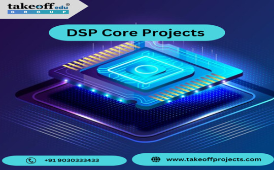
Unique DSP (Digital Signal Processing) core projects For Final year Student
DSP (Digital Signal Processing) core projects are about using clever technology to make signals better. Takeoff Edu Group Furnishes DSP core Projects with better knowledge. It's like magic for sounds, images, and other signals. In these projects, people use special chips or software to make music sound better, pictures clearer, and even help computers understand speech. It's like having a digital wizard that makes things clearer and sharper. These projects are cool because they can make our phones, cameras, and other devices work even better. They give us clearer calls, nicer pictures, and smarter features.
Digital signal processing (DSP) Cores Projects are based on computers algorithms to manipulate the digital signals such as audio or video to give a meaningful output with respect to their content. The new projects are like digital toolboxes that can help you with almost any imaginable tasks like filtering the noise from audio, or cleaning the image, and always minimizing the data size to save storage. Can you assume that the individual is speaking to you via a medium that is not so clear? A project of the DSP would be helpful due to the fact that the audio is degraded and noise removal is the only way to hear the person's voice. Perhaps you could talk about an instance of image processing.
Here are the example titles of DSP Core Projects- Takeoff Projects
Latest
Implementation of Delayed LMS algorithm based Adaptive filter using Verilog HDL
Trendy
Algorithm Level Error Detection in Low Voltage Systolic Array
VLSI Implementation of Turbo Coder for LTE using Verilog HDL
VLSI Implementation of Fully Parallel and CSD FIR Filter Architecture
A High-Speed Floating-Point Multiply-Accumulator Based on FPGAs
High performance IIR filter implementation on FPGA
Standard
An Efficient Parallel DA-Based Fixed-Width Design for Approximate Inner-Product Computation.
Calculator Interface Design in Verilog HDL using MIPS32 Microprocessor.
An Improved Distributed Multiplier-Less Approach for Radix-2 FFT
FPGA Implementation for the Multiplexed and Pipelined Building Blocks of Higher Radix-2k FFT
Low-complexity Continuous-flow Memory-Based FFT Architectures for Real-valued Signals
If there is a picture flattened out, its sharpness could be improved in the project of DSP (Digital signal processing) which would make the photo to look clearer and easier to see the details. These projects are mainly about programming and utilizing software or a specialized physical hardware for the operations of algorithm that process specific frequencies. DSP Core has the potential to be used to solve a wide variety of problems, such as in the fields of communications, medical imaging, and audio processing, and so on. They are instrumental for application of signal polishing and obtaining unique data from the signals, thus simplifying analysis process by rendering it easy to comprehend and work with.
In conclusion, DSP Core projects are essential for many modern technologies, making things like smartphones, music players, and even medical devices work efficiently. Takeoff Edu Group also providing all kind of projects to your Academic years. Through this technology, we can enjoy clearer audio, sharper images, and faster data processing. DSP Core projects play a crucial role in shaping our digital world, enhancing our everyday experiences, and driving innovation forward.
#DSP Memory#Processor core IP#DSP cores Projects#Configurable cores#Configurable processors#DSP core IP core#Digital signal processors
0 notes
Text
youtube
My job as an FPGA (field programmable gate array) engineer can be hard to describe at times. A large part of the confusion comes from understanding what FPGAs are and what they are capable of. FPGAs can be thought of as an large array of lookup tables (LUTs) for binary logic operations that can have their input and output connected together in any concievable combination. This is limited by the routing algorithms efficiency and the amount of resources (clock busses, number of lookup tables, peripherals, etc.) . This animation helps elucidate at least one aspect.
The animation is good at showing how processors have a very limited amount of operations they can perform on binary numbers whereas FPGAs have an unlimited amount of possible operations. The hardware structures that perform computations are what I specify using Verilog. Verilog is a hardware description (programming) language, abbreviated to HDL, which means that what I am functionally doing at work is programming. The distinguishing factor from regular programming (think languages like C, python, JavaScript) is that I am not programming in a language that will compile to instructions for a CPU, but I am instead defining the computation capabilities of an FPGA.
This then requires a host of other devices in order to give the computation I am defining within the FPGA context and make it controllable. These last two parts of the system, control and context, are highly application dependent. I currently work within the wireless communications sector but have worked in electronics test and instrumentation. These sectors themselves would warrant a whole blog post for description of the context they create for FPGA usage. The implication of these contexts and control requirements is that I also need to create Linux distributions, firmware for microcontrollers, and custom printed circuit boards. So all of that can be contained in a single FPGA engineer's responsibilities. In order to create a functioning system utilizing an FPGA, you need to understand the interactions of all of these components because they all interfere directly with eachother. The reason my title is FPGA engineer and not electronics engineer is because most electronics engineers would not know how to program an FPGA.
In some instances, there are entire teams or companies focused around developing designs for FPGAs. That is not the case where I work, though there is an argument for the expansion of my team in that direction.
#c#e#then add engineers as people to the mix and the poor communication style of many of them and here you have a snapshot of my life
0 notes
Text
Advantages of Pursuing Electronics and Communication Engineering
Best Engineering College in Jaipur Rajasthan has courses in Engineering it is the science, skill, and profession of acquiring and applying scientific, economic, social, and practical knowledge, in origin and also building structures, machines, devices, systems, materials, and processes.
Electronics & Communication Engineering deals with electronic devices, circuits, communication equipment & receiver), integrated circuits (IC), basic electronica analog digital transmission & reception of data, voice, and, video.
Why Study ECE?
Best paid jobs best payable life and respect in the society
Job satisfaction
Global career – works with different worlds on common fact
Variety of career opportunities
Challenging work
Problems will be open-ended
You find a solution and persuade others that yours is the best one.
Respect
Intellectual Development
Develops your ability to think logically and to solve problems for The benefit of society You can choose projects that benefit society and also Clean the environment carbon-free. Developing prosthetic aids for disabled persons and Finding new sources of energy also Financial security so You will be well paid and Engineering graduates receive the highest starting salary of any discipline, Prestige, Engineers greatly help and sustain our nation's international competitiveness also maintain our standard of living ensure strong national security and protect public safety.
Professional Environment & Creative Thinking
Engineers need to think creatively is greater than ever before.
Technological And Scientific Discovery
Why do only fa ew elements s behave as semiconductors
Engineering education can help you understand many things in the world of electronics.
Different Roles, Different Names
Research and Development (R&D): Engineers whose role is to do research and then plan for new products, materials, processes parts, and processes
Production: Supervise the manufacturing of electrical and electronic components and machines.
Analysis and testing: Analyse and test different types of machines and their parts to ensure that they function flawlessly.
Installation: Install electrical machines, instruments, and parts at the client’s location.
Operation &Maintenance: Primary role is to ensure that machinery is working as per specifications
Skill Set Required For Getting Jobs
Project management skills
High level of technical expertise
Good communication skills
Leadership capability
Strong analytical skills
Problem-solving capabilities
Practical/resourceful
Creativity (invention, innovation, thinking outside box)
Why Focus On Practical Knowledge?
Gap the happen engineering course content and the requirements of the engineering services industry
Various system imparts knowledge of various technical/non-technical areas, but it often falls short of meeting the expectations of the real world.
The gap is a fundamental lacuna in the engineering education framework and This is the only profession.
Fresh graduates ramped up quickly to productivity is a key concern across the industry, and graduates sometimes take six months to a year to become productive.
What Should You Do?
Pay attention to the basics
Strong foundation in the basics of electronics is a must, and Good knowledge of electronic devices and RF, analog Digital and especially CMOS design also Expertise in VLSI, VHDL, FP and systems, and power transmission verification techniques.
Languages, one must be familiar with HDL (Verilog or VHDL), C and C++, and Other skills - domain knowledge of microprocessors, control systems, embedded systems, and circuit and device testing
Get trained to have an extra edge, also Curriculum may not provide all the learning you need.
Work on a system-level design using off-the-shelf ICs The demand for electronics design engineers to have, the domain also software tools expertise is high.
Actively look out for competitions that organizations/educational institutes conduct Initiatives are excellent opportunities to demonstrate creativity, secure mentoring opportunities from industry experts and pa, and participate in exciting, competitive.
Problem-solving and decision-making, abilities, English Communication skills, and organizational management skills for an all-round perspective.
Exploit Your Internship
Unfortunately, many students treat these courses lightly and My advice would be to take the internship seriously, for the soft skills they impart will be invaluable Keep in mind and Grab every opportunity to chat with everyone from senior members to fresh recruits and You’ll learn a lot about the industry, the job, and their expectations.
Know The Industry Trend
Need to be conversant with global trends and pioneering research worldwide To acquaint himself with the challenges that will face in the future, the engineering student should re-examine.
The electronics industry is very large today and there are multiple sub-disciplines Even some software disciplines require a sound knowledge of electronics along with a strong grip on programming.
Understand Your Aptitude
Companies are looking for people who can fix problems with minimal direction and They don’t want to have to tell people to react when fires are burning.
Conclusion
Top Engineering College in Rajasthan says many opportunities – plan your focused area, Work on both mini and major projects also get a deep insight into the technology, and also Write papers for reviewed journals and conferences. Volunteer speaking on your specialized area, Read, Read and Read and Do not postpone the activity and try to finish on the defined date. Work in the team for the project and share ideas, also Be sincere, hard work, and with a good attitude and Look for clarification if you have doubts, so Get one or two internship projects with the industry.
Source : Click Here
#best btech college in jaipur#top engineering college in jaipur#best btech college in rajasthan#best private engineering college in jaipur#best engineering college in rajasthan#best engineering college in jaipur
0 notes
Text
DLX Verilog Design Laboratory Exercise 4 Solution
In this assignment, you are asked to complete the design of a RISC microprocessor called the DLX. The processor specifications are taken from the book Computer Architecture: A Quantitative Approach by David A. Patterson and John L. Hennessy. You are asked to design two of the pipeline blocks at the HDL level. These blocks would then be combined with the code for the rest of the chip (provided to…

View On WordPress
0 notes
Text
SystemVerilog: Tanım ve Özellikleri
SystemVerilog, donanım tanımlama dili (HDL) olarak kullanılan bir programlama dilidir. Bu dili kullanan donanım tasarımcıları, karmaşık entegre devrelerin (IC) tasarımı ve doğrulamasını gerçekleştirmek için kullanır.
SystemVerilog HDL, asenkron, senkron ve karmaşık donanım tasarımlarını gerçekleştirmek için kullanılan bir dil olarak endüstri standartlarından biridir. Bu dil, sistem seviyesi modüllerin tanımlanması, özellik tabanlı sınıflar, sınamaların şekillendirilmesi ve verilerin toplanması gibi farklı işlevleri yerine getirebilir.
SystemVerilog'in kullanımı yalnızca donanım tasarımı ve doğrulama alanlarıyla sınırlı değildir. Aynı zamanda yazılım ekipleri tarafından geliştirilen test senaryoları ve doğrulama metodları için de kullanılır.
Bu programlama dilinin, donanım ve yazılım arasındaki etkileşimi ve doğrulama süreçlerini optimize etme konusundaki yetenekleri, onu endüstride tercih edilen bir seçenek haline getirmiştir.
SystemVerilog'in Tarihçesi ve Gelişimi
SystemVerilog, Donanım Tanımlama Dili (HDL) için genel amaçlı bir programlama dili olarak kullanılır. Tarihçesi, Verilog-2005'in bir genişlemesi olarak başlar. İlk olarak Accellera tarafından geliştirilmiş ve standartlaştırılmıştır.
SystemVerilog'in gelişimi, ilk olarak 2002 yılında Accellera tarafından başlatılmıştır. Burada, öncelikle Verilog-2005'in gelişmiş versiyonları üzerinde çalışılmıştır. Bu süreçte, dilden türetilen çeşitli yazılım paketleri ve kütüphaneler geliştirilmiştir. Böylece, dili donanım tasarımı ve doğrulama konularında daha etkili ve verimli hale getirmek amaçlanmıştır.
SystemVerilog'in tarihçesindeki bir diğer dönüm noktası ise 2005 yılında IEEE tarafından yapılan standartlaştırmadır. Bu sayede, dili kullanacak olan tüm donanım tasarımcıları ve doğrulama mühendisleri için ortak bir dil ve kurallar belirlenmiş, bu sayede dilin kullanımı ve gelişimi daha da ilerlemiştir.
SystemVerilog'in gelişimi günümüzde de devam etmektedir. Yeni teknolojilere uyum sağlamak, güncel ihtiyaçları karşılamak ve endüstrideki pratik uygulamalara cevap vermek adına sürekli yeni versiyonlar ve güncellemeler yapılmaktadır.
SystemVerilog ile Donanım Tanımlama Dili (HDL) KullanımıSystemVerilog ile donanım tanımlama dili (HDL), karmaşık dijital sistemlerin tasarımı ve doğrulanması için kullanılan bir programlama dili ve donanım tanımlama dili (HDL) uzantısıdır. Bu dili kullanarak, mantıksal ve fiziksel tasarım yapıları, modüller ve entegrasyonlar yapılabilir. Bu da sistemlerin güvenilirliği, ölçeklenebilirliği ve verimliliğini artırır.Bu programlama dili, tasarım ve doğrulama sürecinde tasarımcılara yüksek seviyede kontrol ve esneklik sunar. Aynı zamanda doğrulama metodolojilerini de destekler. SystemVerilog, modern dijital tasarımın gereksinimlerini karşılayacak bir dildir.SystemVerilog ile donanım tanımlama dili (HDL) kullanımı, modern elektronik sistemlerin tasarımı ve doğrulamasında oldukça önemlidir. Bu dilin kullanılması, sistem tasarımcılarının karmaşık sistemleri daha hızlı bir şekilde tasarlamalarına ve doğrulamalarına olanak tanır. Aynı zamanda hem işlevsel doğrulama hem de formal doğrulama için geniş bir modelleme bağlamı sunar.Bu dili öğrenme ve kullanma sürecinde, katmanlı tasarım yapının avantajlarından yararlanarak, donanım tanımlama dili (HDL) kodları modüler bir şekilde oluşturulabilir ve entegre edilebilir. Bu da sistemlerin daha iyi bir yapısal organizasyon ve bakımını sağlar.SystemVerilog'de Modüller ve Tasarımların YapısıSystemVerilog, karmaşık donanımların tasarımı ve doğrulaması için kullanılan bir programlama dilidir. Modüller, SystemVerilog'de tasarımların yapısını oluşturan temel yapı taşlarıdır. Bu modüller, donanım tasarımının farklı bileşenlerini temsil eder ve genellikle birbirleriyle etkileşim içinde çalışırlar.SystemVerilog'de modüller, veri tipleri, portlar, parametreler ve fonksiyonları içerebilir. Bu özellikler sayesinde modüller, donanım tasarımında yeniden kullanılabilirlik ve modülerlik sağlar. Ayrıca,
modüler tasarımın sağladığı hiyerarşik yapı sayesinde daha karmaşık tasarımların yönetimi ve anlaşılması kolaylaşır.Modüler yapılar aynı zamanda eşzamanlı donanım tasarımı için de avantaj sağlar. Bu sayede farklı bileşenlerin aynı anda çalışabilmesi ve haberleşebilmesi mümkün olur. Bu da SystemVerilog'de modüllerin ve tasarımların yapısının önemini gösterir.SystemVerilog'de modüllerin ve tasarımların yapısının iyi anlaşılması, donanım mühendislerinin daha verimli ve sürdürülebilir tasarımlar oluşturmalarına yardımcı olur. Ayrıca, bu yapılar sayesinde donanımın doğrulanması ve test edilmesi süreci de daha etkili hale gelir.SystemVerilog Test Senaryoları ve Doğrulama MetodlarıSystemVerilog test senaryoları ve doğrulama metodları, donanım doğrulama sürecinin kritik bir parçasını oluşturur. Bu adımlar, donanımın beklenen şekilde çalıştığını doğrulamak için yazılım ve donanım mühendisleri tarafından gerçekleştirilir. SystemVerilog'in sağladığı kapsamlı test benzeri yapılar, bu süreci daha da kolaylaştırmaktadır.SystemVerilog, test senaryoları oluşturmak için geniş bir dil yapısına sahiptir. Bu dilin doğrulama metodları, eksiksiz modelleme ve simülasyon olanağı sunar. Bu sayede, donanımın karmaşıklığına uygun seviyede detaylı test senaryoları oluşturulabilir.SystemVerilog'in sağladığı assertions ve coverage özellikleri, test senaryolarının etkinliğini artırır. Assertions, belirli koşulların sağlanıp sağlanmadığını kontrol etmek için kullanılırken, coverage özellikleri ise test senaryolarının donanımın tüm bölümlerini kapsayıp kapsamadığını kontrol etmek için kullanılır.SystemVerilog ile gerçekleştirilen test senaryoları ve doğrulama metodları, donanımın güvenilirliğini artırır ve hataların erken aşamada tespit edilmesini sağlar. Bu sayede, donanımın üretim aşamasına geçmeden önce kaliteli bir şekilde doğrulanması mümkün olur.SystemVerilog'in Sektördeki Uygulama Alanları ve PopülerliğiSystemVerilog, donanım tanımlama dili (HDL) olarak kullanılan bir programlama dilidir. Bu nedenle sektörde geniş bir uygulama alanına sahiptir. Özellikle mikroçip tasarımı ve doğrulama süreçlerinde yaygın olarak kullanılmaktadır. Günümüzde üretim endüstrisinin vazgeçilmez bir parçası haline gelmiştir.SystemVerilog'in popülerliğinin artmasının nedenlerinden biri, karmaşık sistemlerin tasarımı ve doğrulaması için kullanımının kolaylığıdır. Ayrıca, bu dili kullanan uzmanların endüstrinin ihtiyaçlarına daha iyi cevap verebildiği bilinmektedir. Bu da SystemVerilog'in sektördeki popülerliğini artıran etkenlerden biridir. Ayrıca, SystemVerilog ile geliştirilen donanım tasarımlarının yüksek performanslı ve güvenilir olması, bu dilin sektördeki uygulama alanlarını genişletmektedir.SystemVerilog'in endüstriyel uygulama alanlarından biri de otomotiv endüstrisidir. Otomotiv sektöründe elektronik sistemlerin karmaşıklığının artması, bu alanda SystemVerilog'in kullanımını zorunlu hale getirmiştir. Ayrıca, tüketici elektroniği, telekomünikasyon ve savunma sanayi gibi farklı sektörlerde de SystemVerilog'in kullanımı oldukça yaygındır.Bu nedenlerden dolayı, SystemVerilog uzmanlarına olan talep her geçen gün artmakta ve dilin sektördeki uygulama alanları ve popülerliği giderek genişlemektedir. Dolayısıyla, donanım tasarımı ve doğrulama süreçlerinde yer almak isteyen mühendislerin SystemVerilog'i öğrenmeleri ve uzmanlaşmaları, kariyerlerini olumlu yönde etkileyecektir.
0 notes
Text
Online VLSI Design & Verification | Maven Silicon
Online VLSI Design Training - Be a Certified VLSI Engineer with best Online VLSI courses covering Digital Design, SoC Design, Static Timing Analysis, SystemVerilog, Verilog HDL, UVM, Chip Design.
0 notes
Text
Can VHDL and Verilog be enhanced for FPGAs?
Ada, a highly tightly typed and densely typed hardware description language, is where VHDL got its start. VHDL is far more verbose than Verilog, another HDL, as a result of the language requirement, which also increases the number of self-documenting designs. Strong typing in VHDL makes ensuring that explicit datatype conversions, like going from a bit-vector to an integer, happen. VHDL is…

View On WordPress
0 notes
Link
Digital Design: With an Introduction to the Verilog HDL, VHDL, and SystemVerilog 6th Edition, ISBN-13: 978-0134549897 [PDF eBook eTextbook] Publisher: Pearson; 6th edition (March 7, 2017) Language: English 720 pages ISBN-10: 9780134549897 ISBN-13: 978-0134549897 The speed, density, and complexity of today’s digital devices are made possible by advances in physical processing technology and digital design methodology. Aside from semiconductor technology, the design of leading-edge devices depends critically on hardware description languages (HDLs) and synthesis tools. Three public-domain languages, Verilog, VHDL, and SystemVerilog, all play a role in design flows for today’s digital devices. HDLs, together with fundamental knowledge of digital logic circuits, provide an entry point to the world of digital design for students majoring in computer science, computer engineering, and electrical engineering. In the not-too-distant past, it would be unthinkable for an electrical engineering student to graduate without having used an oscilloscope. Today, the needs of industry demand that undergraduate students become familiar with the use of at least one hardware description language. Their use of an HDL as a student will better prepare them to be productive members of a design team after they graduate. Given the presence of three HDLs in the design arena, we have expanded our presentation of HDLs in Digital Design to treat Verilog and VHDL, and to provide an introduction to SystemVerilog. Our intent is not to require students to learn three, or even two, languages, but to provide the instructor with a choice between Verilog and VHDL while teaching a systematic methodology for design, regardless of the language, and an optional introduction to SystemVerilog. Certainly, Verilog and VHDL are widely used and taught, dominate the design space, and have common underlying concepts supporting combinational and sequential logic design, and both are essential to the synthesis of high-density integrated circuits. Our text offers parallel tracks of presentation of both languages, but allows concentration on a single language. The level of treatment of Verilog and VHDL is essentially equal, without emphasizing one language over the other. A language-neutral presentation of digital design is a – common thread through the treatment of both languages. A large set of problems, which are stated in language-neutral terms, at the end of each chapter can be worked with either Verilog or VHDL. The emphasis in our presentation is on digital design, with HDLs in a supporting role. Consequently, we present only those details of Verilog, VHDL, and SystemVerilog that are needed to support our treatment of an introduction to digital design. Moreover, although we present examples using each language, we identify and segregate the treatment of topics and examples so that the instructor can choose a path of presentation for a single language—either Verilog or VHDL. Naturally, a path that emphasizes Verilog can conclude with SystemVerilog, but it can be skipped without compromising the objectives. The introduction to SystemVerilog is selective—we present only topics and examples that are extensions of Verilog, and well within the scope of an introductory treatment. To be clear, we are not advocating simultaneous presentation of the languages. The instructor can choose either Verilog/SystemVerilog or VHDL as the core language supporting an introductory course in digital design. Regardless of the language, our focus is on digital design. The language-based examples throughout the book are not just about the details of an HDL. We emphasize and demonstrate the modeling and verification of digital circuits having specified behavior. Neither Verilog or VHDL are covered in their entirety. Some details of the languages will be left to the reader’s continuing education and use of web resources. Regardless of language, our examples introduce a design methodology based on the concept of computer-aided modeling of digital systems by means of a mainstream, IEEE-standardized, hardware description language. This revision of Digital Design begins each chapter with a statement of its objectives. Problems at the end of each chapter are combined with inchapter examples, and with in-chapter Practice Exercises. Together, these encounters with the subject matter bring the student closer to achieving the stated objectives and becoming skilled in digital design. Answers are given to selected problems at the end of each chapter. A Solution Manual gives detailed solutions to all of the problems at the end of the chapters. The level of detail of the solutions is such that an instructor can use individual problems to support classroom instruction. Table of Contents: Preface 1 Digital Systems and Binary Numbers 1.1 Digital Systems 1.2 Binary Numbers 1.3 NumberBase Conversions 1.4 Octal and Hexadecimal Numbers 1.5 Complements of Numbers 1.6 Signed Binary Numbers 1.7 Binary Codes 1.8 Binary Storage and Registers 1.9 Binary Logic 2 Boolean Algebra and Logic Gates 2.1 Introduction 2.2 Basic Definitions 2.3 Axiomatic Definition of Boolean Algebra 2.4 Basic Theorems and Properties of Boolean Algebra 2.5 Boolean Functions 2.6 Canonical and Standard Forms 2.7 Other Logic Operations 2.8 Digital Logic Gates 2.9 Integrated Circuits 3 GateLevel Minimization 3.1 Introduction 3.2 The Map Method 3.3 FourVariable K-Map 3.4 ProductofSums Simplification 3.5 Don’tCare Conditions 3.6 NAND and NOR Implementation 3.7 Other TwoLevel Implementations 3.8 ExclusiveOR Function 3.9 Hardware Description Languages (HDLs) 4 Combinational Logic 4.1 Introduction 4.2 Combinational Circuits 4.3 Analysis of Combinational Circuits 4.4 Design Procedure 4.5 Binary Adder—Subtractor 4.6 Decimal Adder 4.7 Binary Multiplier 4.8 Magnitude Comparator 4.9 Decoders 4.10 Encoders 4.11 Multiplexers 4.12 HDL Models of Combinational Circuits 5 Synchronous Sequential Logic 5.1 Introduction 5.2 Sequential Circuits 5.3 Storage Elements: Latches 5.4 Storage Elements: FlipFlops 5.5 Analysis of Clocked Sequential Circuits 5.6 Synthesizable HDL Models of Sequential Circuits 5.7 State Reduction and Assignment 5.8 Design Procedure 6 Registers and Counters 6.1 Registers 6.2 Shift Registers 6.3 Ripple Counters 6.4 Synchronous Counters 6.5 Other Counters 6.6 HDL Models of Registers and Counters 7 Memory and Programmable Logic 7.1 Introduction 7.2 RandomAccess Memory 7.3 Memory Decoding 7.4 Error Detection and Correction 7.5 ReadOnly Memory 7.6 Programmable Logic Array 7.7 Programmable Array Logic 7.8 Sequential Programmable Devices 8 Design at the Register Transfer Level 8.1 Introduction 8.2 Register Transfer Level (RTL) Notation 8.3 RTL descriptions VERILOG (Edge- and Level-Sensitive Behaviors) 8.4 Algorithmic State Machines (ASMs) 8.5 Design Example (ASMD Chart) 8.6 HDL Description of Design Example 8.7 Sequential Binary Multiplier 8.8 Control Logic 8.9 HDL Description of Binary Multiplier 8.10 Design with Multiplexers 8.11 RaceFree Design (Software Race Conditions) 8.12 LatchFree Design (Why Waste Silicon?) 8.13 System Verilog–An Introduction 9 Laboratory Experiments with Standard ICs and FPGAs 9.1 Introduction to Experiments 9.2 Experiment 1: Binary and Decimal Numbers 9.3 Experiment 2: Digital Logic Gates 9.4 Experiment 3: Simplification of Boolean Functions 9.5 Experiment 4: Combinational Circuits 9.6 Experiment 5: Code Converters 9.7 Experiment 6: Design with Multiplexers 9.8 Experiment 7: Adders and Subtractors 9.9 Experiment 8: FlipFlops 9.10 Experiment 9: Sequential Circuits 9.11 Experiment 10: Counters 9.12 Experiment 11: Shift Registers 9.13 Experiment 12: Serial Addition 9.14 Experiment 13: Memory Unit 9.15 Experiment 14: Lamp Handball 9.16 Experiment 15: ClockPulse Generator 9.17 Experiment 16: Parallel Adder and Accumulator 9.18 Experiment 17: Binary Multiplier 9.19 HDL Simulation Experiments and Rapid Prototyping with FPGAs 10 Standard Graphic Symbols 10.1 RectangularShape Symbols 10.2 Qualifying Symbols 10.3 Dependency Notation 10.4 Symbols for Combinational Elements 10.5 Symbols for FlipFlops 10.6 Symbols for Registers 10.7 Symbols for Counters 10.8 Symbol for RAM Appendix Answers to Selected Problems Index M. Morris Mano is an Emeritus Professor of Computer Engineering at the California State University, Los Angeles. His notable works include the Mano Machine, i.e. a theoretical computer that contains a central processing unit, random access memory, and an input-output bus. M. Morris Mano has authored numerous books in the area of digital circuits that are known for teaching the basic concepts of digital logic circuits in a clear, accessible manner. His books for the introductory digital design course, Logic and Computer Design Fundamentals and Digital Design, continue to be two of the most widely used texts around the world. Michael Ciletti is an Emeritus Professor of Electrical and Computer Engineering at the University of Colorado, Colorado Springs. An early advocate of including HDL-based design methodology in the curriculum, he pioneered and developed the offering of several courses using Verilog, VHDL, FPGAs and standard cell based hardware implementations for design, testing, and synthesis of VLSI devices. His consulting work has ranged from processor design to providing expert witness testimony in cases involving HDLs. He has developed and presented courses for industry in The United States, Asia, and Europe. His widely-adopted textbooks have promoted the use of the now-standard Verilog HDL and encouraged adoption of HDL-based design practice in logic design and computer science curricula. Ciletti resides in Colorado Springs, CO, where he pursues a strong interest in landscape photography. What makes us different? • Instant Download • Always Competitive Pricing • 100% Privacy • FREE Sample Available • 24-7 LIVE Customer Support
0 notes
Text
youtube
VHDL Basics : Begin the World of FPGA Design Tools & VHDL Design Flow
Welcome to our comprehensive guide on FPGA design tools and VHDL design flow! In this video, we dive into the fascinating world of FPGA design and explore the essential tools and methodologies needed for successful FPGA development. Whether you're a beginner or an experienced engineer, this tutorial will provide valuable insights and tips to enhance your FPGA design skills. We start by introducing the fundamentals of FPGA design, explaining the benefits and versatility of using FPGAs in various applications. From there, we explore the wide range of design tools available, from popular industry-standard software like Xilinx Vivado and Altera Quartus Prime to open-source alternatives like GHDL and Icarus Verilog. We highlight the strengths and features of each toolset, enabling you to choose the most suitable one for your projects. With a solid foundation in FPGA design and tools, we then delve into the VHDL (VHSIC Hardware Description Language) design flow. From understanding the basics of VHDL syntax to implementing complex digital designs, we provide step-by-step explanations and practical demonstrations. You'll learn about entity and architecture design, the importance of libraries, and how to simulate and synthesize VHDL code for your FPGA. To ensure a holistic learning experience, we discuss common challenges and pitfalls in FPGA design and provide valuable troubleshooting tips. We also touch upon advanced topics like FPGA optimization techniques, timing analysis, and physical implementation considerations. So, whether you're a student, hobbyist, or professional looking to enhance your FPGA design skills, this tutorial is the ultimate resource to get started on your journey. Join us now and unlock the vast potential of FPGA design tools and the VHDL design flow! FPGA design tools, VHDL design flow, FPGA development, Xilinx Vivado, Altera Quartus Prime, VHDL, Verilog, VHDL syntax, digital design, entity architecture, libraries, simulate VHDL code, synthesize VHDL code, FPGA optimization techniques, timing analysis, physical implementation, FPGA design skills.
Subscribe to "Learn And Grow Community"
YouTube : https://www.youtube.com/@LearnAndGrowCommunity
LinkedIn Group : https://www.linkedin.com/groups/7478922/
Blog : https://LearnAndGrowCommunity.blogspot.com/
Facebook : https://www.facebook.com/JoinLearnAndGrowCommunity/
Twitter Handle : https://twitter.com/LNG_Community
DailyMotion : https://www.dailymotion.com/LearnAndGrowCommunity
Instagram Handle : https://www.instagram.com/LearnAndGrowCommunity/
Follow #LearnAndGrowCommunity
#HDL Design#Digital Design#Verilog#VHDL#FPGA#Simulation#Synthesis#B.Tech#VLSI#Training#Career#ASIC#Xilinx#Students#hardware description language#VHDL tutorial#VHDL beginner guide#VHDL syntax#VHDL data types#VHDL modeling#behavioral modeling#data flow modeling#FSM#FPGA design tools#VHDL design flow#FPGA development#Xilinx Vivado#Altera Quartus Prime#entity#architecture
1 note
·
View note
Text
Best VLSI - Finite State Machines Projects for engineering students
In the dynamic landscape, Finite State Machine Project provide a systematic means of represented the dynamic world of network with a finite number of distinct condition. These states summarize specific design or modes of province that the system may reside at any given moment. Takeoff Edu Group provides this projects with innovative and unique titles. Conversion between states report the growth of the system's behaviour in response to stimuli or events, change the essence of approach dynamics.
Finite State Machines (FSMs) are basic models used in computer science and engineering to understand how systems work. They show the different situations a system can be in, how it changes between these situations, and what actions it takes. Visual diagrams, like state transition diagrams, help us understand FSMs better. These diagrams show how the situations are connected and help us see important points in how the system behaves.

The Example Title of Finite State Machine Project –Takeoff Edu Groups
Trendy:
Fully Automated Traffic Light Controller system for a four-way intersection using Verilog
Experience seamless traffic flow with our Fully Automated Traffic Light Controller system designed for four-way intersections. Built using Verilog, our solution ensures efficient and safe navigation for vehicles and pedestrians alike
Approach for Implementation of Vending Machine through Verilog HDL
Implementing a Vending Machine using Verilog HDL: A robust approach for digital logic design enthusiasts to create efficient vending solutions. Harnessing Verilog HDL's power, this implementation ensures seamless operation and precise functionality
Design and implementation of subway automatic ticketing system based on Verilog HDL
Revolutionize urban commuting with our Verilog HDL-based Subway Automatic Ticketing System. Seamlessly designed and implemented for efficient, hassle-free travel experiences underground. Experience the future of subway ticketing today.
There are two main types of FSMs: deterministic and non-deterministic. Deterministic FSMs have clear rules for how they change between situations. Non-deterministic FSMs have more flexible rules, allowing for different changes from the same situation.
FSMs are useful in many areas, like making software, designing hardware, and building robots. They help us create and understand systems by showing us how they work in different situations. Overall, FSMs are essential tools for engineers to model and understand how systems behave in both theoretical and practical situations.
Finite State Machines projects (FSMs) aren't just models for understanding systems; they're also tools for making new things happen. By using FSMs in Takeoff Edu group and other attempt, we're not just solving problems – we're opening doors to new ideas and progress. As we keep using FSMs to explore and create, we're pushing technology and engineering forward, finding better ways to do things and making exciting discoveries along the way. The Above titles are the examples of Takeoff Edu group Finite State Machines.
#VLSI Projects#Finite State Machine Project#FSM-Applications#Finite State Machines#Final Year projects#Engineering Projects#Academic Projects#ECE Projects.
0 notes
Link
Digital Design: With an Introduction to the Verilog HDL, VHDL, and SystemVerilog 6th Edition, ISBN-13: 978-0134549897 [PDF eBook eTextbook] Publisher: Pearson; 6th edition (March 7, 2017) Language: English 720 pages ISBN-10: 9780134549897 ISBN-13: 978-0134549897 The speed, density, and complexity of today’s digital devices are made possible by advances in physical processing technology and digital design methodology. Aside from semiconductor technology, the design of leading-edge devices depends critically on hardware description languages (HDLs) and synthesis tools. Three public-domain languages, Verilog, VHDL, and SystemVerilog, all play a role in design flows for today’s digital devices. HDLs, together with fundamental knowledge of digital logic circuits, provide an entry point to the world of digital design for students majoring in computer science, computer engineering, and electrical engineering. In the not-too-distant past, it would be unthinkable for an electrical engineering student to graduate without having used an oscilloscope. Today, the needs of industry demand that undergraduate students become familiar with the use of at least one hardware description language. Their use of an HDL as a student will better prepare them to be productive members of a design team after they graduate. Given the presence of three HDLs in the design arena, we have expanded our presentation of HDLs in Digital Design to treat Verilog and VHDL, and to provide an introduction to SystemVerilog. Our intent is not to require students to learn three, or even two, languages, but to provide the instructor with a choice between Verilog and VHDL while teaching a systematic methodology for design, regardless of the language, and an optional introduction to SystemVerilog. Certainly, Verilog and VHDL are widely used and taught, dominate the design space, and have common underlying concepts supporting combinational and sequential logic design, and both are essential to the synthesis of high-density integrated circuits. Our text offers parallel tracks of presentation of both languages, but allows concentration on a single language. The level of treatment of Verilog and VHDL is essentially equal, without emphasizing one language over the other. A language-neutral presentation of digital design is a – common thread through the treatment of both languages. A large set of problems, which are stated in language-neutral terms, at the end of each chapter can be worked with either Verilog or VHDL. The emphasis in our presentation is on digital design, with HDLs in a supporting role. Consequently, we present only those details of Verilog, VHDL, and SystemVerilog that are needed to support our treatment of an introduction to digital design. Moreover, although we present examples using each language, we identify and segregate the treatment of topics and examples so that the instructor can choose a path of presentation for a single language—either Verilog or VHDL. Naturally, a path that emphasizes Verilog can conclude with SystemVerilog, but it can be skipped without compromising the objectives. The introduction to SystemVerilog is selective—we present only topics and examples that are extensions of Verilog, and well within the scope of an introductory treatment. To be clear, we are not advocating simultaneous presentation of the languages. The instructor can choose either Verilog/SystemVerilog or VHDL as the core language supporting an introductory course in digital design. Regardless of the language, our focus is on digital design. The language-based examples throughout the book are not just about the details of an HDL. We emphasize and demonstrate the modeling and verification of digital circuits having specified behavior. Neither Verilog or VHDL are covered in their entirety. Some details of the languages will be left to the reader’s continuing education and use of web resources. Regardless of language, our examples introduce a design methodology based on the concept of computer-aided modeling of digital systems by means of a mainstream, IEEE-standardized, hardware description language. This revision of Digital Design begins each chapter with a statement of its objectives. Problems at the end of each chapter are combined with inchapter examples, and with in-chapter Practice Exercises. Together, these encounters with the subject matter bring the student closer to achieving the stated objectives and becoming skilled in digital design. Answers are given to selected problems at the end of each chapter. A Solution Manual gives detailed solutions to all of the problems at the end of the chapters. The level of detail of the solutions is such that an instructor can use individual problems to support classroom instruction. Table of Contents: Preface 1 Digital Systems and Binary Numbers 1.1 Digital Systems 1.2 Binary Numbers 1.3 NumberBase Conversions 1.4 Octal and Hexadecimal Numbers 1.5 Complements of Numbers 1.6 Signed Binary Numbers 1.7 Binary Codes 1.8 Binary Storage and Registers 1.9 Binary Logic 2 Boolean Algebra and Logic Gates 2.1 Introduction 2.2 Basic Definitions 2.3 Axiomatic Definition of Boolean Algebra 2.4 Basic Theorems and Properties of Boolean Algebra 2.5 Boolean Functions 2.6 Canonical and Standard Forms 2.7 Other Logic Operations 2.8 Digital Logic Gates 2.9 Integrated Circuits 3 GateLevel Minimization 3.1 Introduction 3.2 The Map Method 3.3 FourVariable K-Map 3.4 ProductofSums Simplification 3.5 Don’tCare Conditions 3.6 NAND and NOR Implementation 3.7 Other TwoLevel Implementations 3.8 ExclusiveOR Function 3.9 Hardware Description Languages (HDLs) 4 Combinational Logic 4.1 Introduction 4.2 Combinational Circuits 4.3 Analysis of Combinational Circuits 4.4 Design Procedure 4.5 Binary Adder—Subtractor 4.6 Decimal Adder 4.7 Binary Multiplier 4.8 Magnitude Comparator 4.9 Decoders 4.10 Encoders 4.11 Multiplexers 4.12 HDL Models of Combinational Circuits 5 Synchronous Sequential Logic 5.1 Introduction 5.2 Sequential Circuits 5.3 Storage Elements: Latches 5.4 Storage Elements: FlipFlops 5.5 Analysis of Clocked Sequential Circuits 5.6 Synthesizable HDL Models of Sequential Circuits 5.7 State Reduction and Assignment 5.8 Design Procedure 6 Registers and Counters 6.1 Registers 6.2 Shift Registers 6.3 Ripple Counters 6.4 Synchronous Counters 6.5 Other Counters 6.6 HDL Models of Registers and Counters 7 Memory and Programmable Logic 7.1 Introduction 7.2 RandomAccess Memory 7.3 Memory Decoding 7.4 Error Detection and Correction 7.5 ReadOnly Memory 7.6 Programmable Logic Array 7.7 Programmable Array Logic 7.8 Sequential Programmable Devices 8 Design at the Register Transfer Level 8.1 Introduction 8.2 Register Transfer Level (RTL) Notation 8.3 RTL descriptions VERILOG (Edge- and Level-Sensitive Behaviors) 8.4 Algorithmic State Machines (ASMs) 8.5 Design Example (ASMD Chart) 8.6 HDL Description of Design Example 8.7 Sequential Binary Multiplier 8.8 Control Logic 8.9 HDL Description of Binary Multiplier 8.10 Design with Multiplexers 8.11 RaceFree Design (Software Race Conditions) 8.12 LatchFree Design (Why Waste Silicon?) 8.13 System Verilog–An Introduction 9 Laboratory Experiments with Standard ICs and FPGAs 9.1 Introduction to Experiments 9.2 Experiment 1: Binary and Decimal Numbers 9.3 Experiment 2: Digital Logic Gates 9.4 Experiment 3: Simplification of Boolean Functions 9.5 Experiment 4: Combinational Circuits 9.6 Experiment 5: Code Converters 9.7 Experiment 6: Design with Multiplexers 9.8 Experiment 7: Adders and Subtractors 9.9 Experiment 8: FlipFlops 9.10 Experiment 9: Sequential Circuits 9.11 Experiment 10: Counters 9.12 Experiment 11: Shift Registers 9.13 Experiment 12: Serial Addition 9.14 Experiment 13: Memory Unit 9.15 Experiment 14: Lamp Handball 9.16 Experiment 15: ClockPulse Generator 9.17 Experiment 16: Parallel Adder and Accumulator 9.18 Experiment 17: Binary Multiplier 9.19 HDL Simulation Experiments and Rapid Prototyping with FPGAs 10 Standard Graphic Symbols 10.1 RectangularShape Symbols 10.2 Qualifying Symbols 10.3 Dependency Notation 10.4 Symbols for Combinational Elements 10.5 Symbols for FlipFlops 10.6 Symbols for Registers 10.7 Symbols for Counters 10.8 Symbol for RAM Appendix Answers to Selected Problems Index M. Morris Mano is an Emeritus Professor of Computer Engineering at the California State University, Los Angeles. His notable works include the Mano Machine, i.e. a theoretical computer that contains a central processing unit, random access memory, and an input-output bus. M. Morris Mano has authored numerous books in the area of digital circuits that are known for teaching the basic concepts of digital logic circuits in a clear, accessible manner. His books for the introductory digital design course, Logic and Computer Design Fundamentals and Digital Design, continue to be two of the most widely used texts around the world. Michael Ciletti is an Emeritus Professor of Electrical and Computer Engineering at the University of Colorado, Colorado Springs. An early advocate of including HDL-based design methodology in the curriculum, he pioneered and developed the offering of several courses using Verilog, VHDL, FPGAs and standard cell based hardware implementations for design, testing, and synthesis of VLSI devices. His consulting work has ranged from processor design to providing expert witness testimony in cases involving HDLs. He has developed and presented courses for industry in The United States, Asia, and Europe. His widely-adopted textbooks have promoted the use of the now-standard Verilog HDL and encouraged adoption of HDL-based design practice in logic design and computer science curricula. Ciletti resides in Colorado Springs, CO, where he pursues a strong interest in landscape photography. What makes us different? • Instant Download • Always Competitive Pricing • 100% Privacy • FREE Sample Available • 24-7 LIVE Customer Support
0 notes
Text
VHDL'nin temel prensipleri
VHDL, Verilog HDL ile birlikte dijital sistemlerin tasarımı için kullanılan en popüler programlama dillerinden biridir. VHDL'nin temel prensipleri, dijital devrelerin ve sistemlerin tasarımı için gereken temel adımları ve yönergeleri içerir. Bu prensipler, tasarımı yapılan sistemlerin doğruluğunu ve güvenilirliğini sağlamak için çok önemlidir.
VHDL tasarım prensipleri, genellikle modülerlik, kapsülleme, doğruluk ve tasarımın tekrar kullanılabilirliği gibi temel kavramlar etrafında döner. Her bir modülün kendi işlevselliğine ve veri yolu arayüzlerine sahip olması, tasarım sürecini kolaylaştırır ve hata ayıklamayı basitleştirir.
VHDL'nin temel prensipleri, tasarımın başlangıcından bitişine kadar olan tüm aşamaları kapsar. Bu aşamalar arasında problemin analizi, tasarımın modüler bloklara ayrılması, modüller arasındaki iletişimin sağlanması, doğrulamanın yapılması ve son olarak sentez aşamasına geçilmesi bulunur.
Tüm bu prensipler, VHDL'nin dijital tasarım sürecinde etkili ve verimli bir şekilde kullanılmasını sağlar. Düzgün bir şekilde uygulandığında, VHDL tasarımları istenilen sonuçları verir ve geliştirme sürecini hızlandırır.
VHDL'nin kullanım alanları
VHDL, yüksek seviyeli bir programlama dilidir ve genellikle dijital donanım tasarımı için kullanılır. Birçok farklı sektörde VHDL'nin kullanım alanları bulunmaktadır. Özellikle askeri, telekomünikasyon, tıp, otomotiv ve bilgisayar endüstrisi gibi sektörlerde sıkça kullanılmaktadır.
VHDL, karmaşık donanımların tasarımı, doğrulaması ve simülasyonunda yaygın olarak kullanılmaktadır. Bu dil, programlanabilir mantık cihazları (PLD), sayısal sinyal işleme (DSP) ve veri iletimi gibi alanlarda da tercih edilmektedir.
VHDL'nin kullanım alanları arasında ayrıca entegre devre tasarımı, FPGA programlama, mikroişlemci sistemleri, ASIC (Application-Specific Integrated Circuit) tasarımı gibi alanlar da bulunmaktadır. Elektronik, haberleşme ve otomasyon sistemleri de VHDL'nin kullanım alanları içerisinde yer almaktadır.
VHDL, donanım tasarımının karmaşıklığını azaltmaya ve gelişmiş tasarım yetenekleri ile yüksek performanslı sistemlerin geliştirilmesine olanak sağlamaktadır. Bu nedenle VHDL'nin kullanım alanları her geçen gün genişlemekte ve farklı sektörlerde farklı uygulamaları bulunmaktadır.
VHDL'nin avantajları ve dezavantajlarıVHDL, tasarım sürecindeki adımları tanımlamak ve karmaşık donanımın modellenmesine izin vermek gibi birçok avantajı vardır. Tasarım sürecini kolaylaştırarak, geliştirme süresini kısaltabilir ve üretkenliği artırabilir. Bununla birlikte, VHDL'nin bazı dezavantajları da vardır. Örneğin, öğrenilmesi ve anlaşılması zor olabilir. Ayrıca, günümüzde daha modern ve yüksek seviye diller bulunduğu için, VHDL'nin kullanım alanı zamanla daralmış olabilir.VHDL'nin bir avantajı, karmaşık donanım modelleri oluşturmak ve tasarım sürecini simüle etmek için kullanılabilmesidir. Bu, tasarım hatalarını erken aşamada tespit etmek ve maliyetleri azaltmak için çok önemlidir. Ayrıca, VHDL tasarımı, tekrar kullanılabilirlik ve modülerlik sağlar, böylece büyük ölçekli projelerde kullanımı oldukça faydalıdır.VHDL'nin dezavantajları arasında ilk olarak öğrenme eğrisi gelir. Dilin karmaşıklığı ve soyutluğu, başlangıçta öğrenmeyi zorlaştırabilir. Ayrıca, günümüzde daha modern dillerin bulunması nedeniyle, VHDL kullanım alanı zamanla daralmış olabilir. Bu da VHDL öğrenme ve kullanma motivasyonunu azaltabilir. Bununla birlikte, VHDL'nin avantajları ve dezavantajları göz önüne alındığında, endüstri standardı olarak hala oldukça önemli bir rol oynamaktadır. Bilhassa donanım tasarımı ve simülasyonu alanlarında, VHDL'nin faydaları hala çokça tercih edilmesine neden olmaktadır.VHDL öğrenmek için kaynaklarVHDL, donanım tanımlama dilinin (HDL) bir türüdür. VHDL öğrenmek isteyenler için birçok kaynak bulunmaktadır. Bu kaynaklar, kitaplar, online kurslar, eğitim videoları ve pratik projelerin bulunduğu platformlardan oluşmaktadır. VHDL öğrenmek için en iyi kaynaklardan biri, konuyla ilgili uzmanlaşmış bir eğitmenin rehberliğinde online kurslardır.
Bu kurslarda, temel konseptlerden başlayarak VHDL dilinin kullanımı, donanım tasarımı ve simülasyonu gibi konular detaylı bir şekilde ele alınmaktadır.Kitaplar da VHDL öğrenmek isteyenler için çok değerli kaynaklardır. VHDL ile donanım tasarımı ve simülasyonu konularında uzmanlaşmış yazarlar tarafından yazılmış kitaplar, konuya daha derinlemesine hakim olmak isteyenler için oldukça faydalı olacaktır.Ayrıca internet üzerinde birçok ücretsiz VHDL kaynağı bulunmaktadır. Bu kaynaklar arasında, VHDL dilinin temellerinden ileri düzey konseptlere kadar geniş bir yelpazede bilgi sunan blog yazıları, video dersleri ve forumlar yer almaktadır.VHDL tasarım süreci adımlarıVHDL tasarım süreci, dijital donanım tasarımı için kullanılan bir programlama dilidir. Bu süreç, belirlenen bir donanımın ihtiyaçlarına göre VHDL kodunun yazılmasını içerir. Tasarım süreci adımları, donanımın ihtiyaçlarına uygun bir şekilde belirlenmelidir.VHDL tasarım süreci adımlarından ilki, tasarım gereksinimlerinin analiz edilmesidir. Bu adımda, donanımın işlevsel gereksinimleri belirlenir ve tasarım için gerekli olan bloklar ve bileşenler tanımlanır.Bir sonraki adım, donanımın tasarımının oluşturulmasıdır. Bu aşamada, VHDL kodu kullanılarak donanımın modelleri oluşturulur ve tasarım gereksinimlerine uygun olarak blokların ve bileşenlerin birbirine bağlanması sağlanır.Tasarım sürecinin bir diğer önemli adımı ise sentez ve simülasyon işlemleridir. Bu adımda, tasarım VHDL sentez araçları kullanılarak sentezlenir ve ardından simülasyon işlemleri gerçekleştirilerek tasarımın doğruluğu kontrol edilir.VHDL ile donanım tasarlama ve simülasyon
VHDL, Donanım Tanımlama Dili'nin (Hardware Description Language) kullanılmasıyla donanım tasarlamak ve simüle etmek mümkün hale gelmektedir. VHDL, karmaşık donanım projelerini tasarlamak ve simüle etmek için oldukça güçlü bir araçtır.
Öncelikle, VHDL'de donanım tasarlamak için gerekli olan blokların tanımlanması gerekmektedir. Bu bloklar, projenin temel yapı taşlarıdır ve her biri ayrı ayrı fonksiyonlarını yerine getirir. Bu blokları doğru bir şekilde tanımlamak, donanımın doğru bir şekilde tasarlanması için oldukça önemlidir.
Ardından, tasarlanan donanımın simülasyonu gerçekleştirilir. VHDL, simüle etmek istediğimiz donanımın davranışlarını ve performansını test etmek için kullanılır. Bu sayede, tasarlanan donanımın gerçek dünyadaki performansı hakkında bilgi sahibi olabiliriz.
VHDL ile donanım tasarlama ve simülasyon, günümüzdeki teknolojik gelişmelerin bir sonucu olarak oldukça önemli bir süreç haline gelmiştir. Bu süreç, endüstride kullanılan pek çok elektronik cihazın geliştirilmesinde ve üretilmesinde temel bir rol oynamaktadır.
0 notes
Text
Learn Verilog HDL | SoC & Digital Design | Maven Silicon
Learn Verilog Online - Enrol for VLSI Design Online Course from Maven Silicon which covers VLSI Design, Verilog HDL, Digital Design & build on-demand VLSI skills to be a hands-on RTL Designer
0 notes
Last Seen Blogs

taylorsnowromancedatinglovesex
Taylor Snow Romance Dating Relationships Love Sex Passion

carsonmell
Tarantula
plantsandothercitizens
Plants & other citizens

tacobelt-blog
3L's and A Pencil

askaccurateaceattorney-blog
Ask (Accurate) Ace Attorney!