#systemverilog
Text
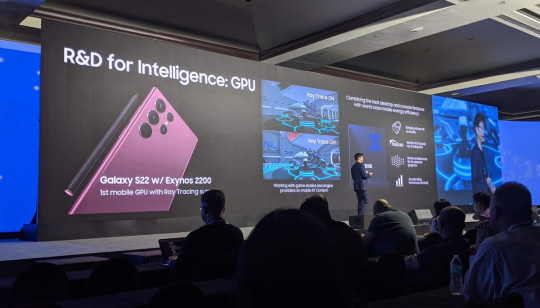
Как подготовиться к собеседованию в Samsung Advanced Computing Lab
Как подготовиться к собеседованию в Samsung Advanced Computing Lab
Я работаю проектировщиком аппаратного блока графического процессора в телефонах Samsung, в рамках совместного проекта с AMD. Сейчас наш менеджмент расширяет команду и поощряет инженеров распостранять информацию о новых позициях среди своих знакомых. Я решил написать это пост для более широкой аудитории, так как множество людей, способных пройти интервью на RTL или DV позицию – больше, чем…
View On WordPress
#GPU#RISC-V#RTL#Samsung#Samsung Advanced Computing Lab#SystemVerilog#Verilog#интервью#Харрис & Харрис
4 notes
·
View notes
Text
celebrating fall with fletcher's checksum
This post originally appeared on my website.
why are checksums useful for fpga development?
Checksum functions are useful for error detection and data integrity. With respect to FPGA architecture development, a checksum can ensure the system is able to retain its state. For example, an FPGA programmed to behave like an AND gate should not start to act like an OR gate due fluctuations in voltage or temperature. Such problems may be caught by computing the checksum of the bitstream before configuring the FPGA, operating the device in the lab, and then extracting the bitstream and re-computing the checksum to ensure it has not changed.
The last two FPGAs that I worked on-with Indiana University's SAIL-IN Lab and the QuickLogic Corporation-used a scan chain configuration interface which lent itself well to bitstream verification via checksum. The scan chain acts like a serial shift register, stringing together all the configuration chain flip-flops in the FPGA fabric. As the bitstream flows through the head of the scan chain, one bit at a time, its checksum may be computed; and later re-computed as it flows out of the tail. For context, imagine a small, thirty-two flop scan chain and the corresponding bitstream, 0xdeadbeef. On the way in, the Fletcher's (32-bit) checksum will be 0xf13b. If the post-configuration checksum does not match, the engineers would know that there is an issue with the FPGA architecture.
Fletcher's checksum also produces check bytes (or a "tag"), which can be appended to the end of the original data, such that the new checksum of the data and the check bytes is zero. For the example bitstream 0xdeadbeef, the resulting check bytes are 0xd2f1. And the checksum of 0xdeadbeefd2f1 is 0x0.
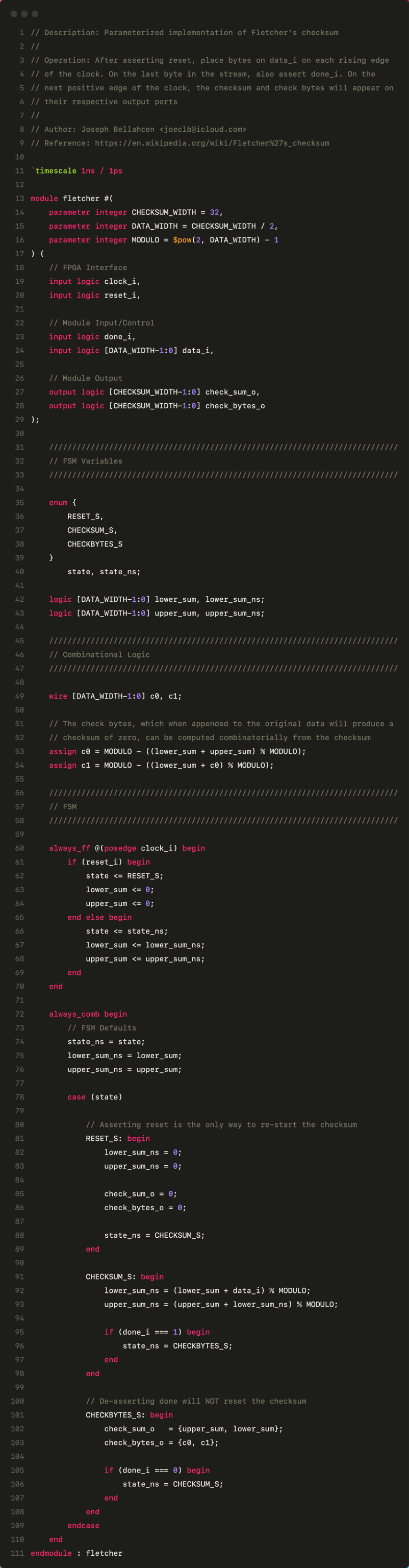
fletcher's checksum in systemverilog
Based mostly on the Wikipedia entry for Fletcher's checksum, I produced a parameterized, three-state module which computes the checksum and check bytes of a data stream. The SystemVerilog closesly follows the below psuedo-code. For the Fletcher-32 checksum, data arrives as 16-bit half-words.
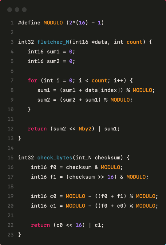
Eventually, I'd like to wrap it in a SPI interface and submit it to TinyTapeout, but for now here's the bare RTL. The most up-to-date code is also available on GitHub:
#engineering#computer engineering#fpga#verilog#systemverilog#hardware design#engineering student#studyblr
0 notes
Text
SystemVerilog Tutorial | Maven Silicon
Enroll for Online VLSI Verification Courses @ Maven Silicon which covers SystemVerilog, UVM, SoC Verification & build expertise in the VLSI skills to get a VLSI job. Online SystemVerilog & UVM Tutorials available!
https://www.maven-silicon.com/online-vlsi-verification-systemverilog-uvm-course/
0 notes
Text
Unlocking the Power of System Verilog Assertions with iSpec.ai
Introduction
Assertions play a pivotal role in hardware verification, both for dynamic (simulation based) verification and formal verification. These assertions, expressed in a specialized language, play a crucial role in ensuring the correctness and reliability of complex digital systems. However, crafting these assertions often requires a deep understanding of both the design under test and the intricacies of the assertion language itself. To simplify this process and empower engineers, Agnisys introduces iSpec.ai, a groundbreaking service that transforms natural English text into SystemVerilog Assertions (SVA) with precision and accuracy.
SystemVerilog Assertions: A Brief Overview
Before exploring iSpec.ai, let's first understand the significance of SystemVerilog Assertions in the verification industry. SVA is essential for engineers, enabling them to formally specify the intended behavior of their designs. By expressing properties and constraints concisely, SVA facilitates rigorous verification, detecting errors early in the design cycle and reducing the risk of costly rework and system failures during deployment. From simple temporal (time based) relationships to complex protocol specifications, SVA empowers engineers to articulate a wide range of design requirements with precision and clarity.
Approaching the Challenge: iSpec.ai
At Agnisys, our mission is to democratize the process of generating SVA, making it accessible to engineers of all backgrounds. We are marching towards our stated vision of automatically creating hardware design directly from specifications. With iSpec.ai, assertions can be easily created from natural language specification, bridging the gap between a natural language and hardware verification.
To achieve this ambitious goal, we leverage state-of-the-art Large Language Models (LLM), renowned for their exceptional ability to understand and map dependencies between input and output sequences. Harnessing the power of machine translation, iSpec.ai transforms English specifications into SVA. In developing iSpec.ai, we have adopted a hybrid approach, combining the principles of prompt engineering and fine-tuning LLMs for downstream tasks. This strategic fusion allows us to leverage the strengths of both methodologies, resulting in a service that excels in generating high-quality assertions tailored to the unique requirements of each user.
Understanding Large Language Models
At the heart of iSpec.ai lies the concept of (LLMs), representing a significant advancement in natural language processing. Built upon transformer architectures, these models possess the remarkable ability to understand and generate human-like text across various languages and domains. Central to the efficacy of LLMs is self-attention, a mechanism that enables the model to weigh the significance of different words in a sentence while generating its output. By attending to relevant context and dependencies within the input sequence, self-attention empowers LLMs to capture intricate patterns and semantics, facilitating accurate and contextually relevant text generation.

Fine-Tuning for Downstream Tasks
While pre-trained LLMs exhibit impressive capabilities out-of-the-box, fine-tuning allows us to tailor these models to specific downstream tasks, such as generating SVA. However, traditional fine-tuning approaches pose significant challenges, particularly in terms of memory and compute requirements.
Historically, Full Fine-Tuning has been the predominant method, involving the updating of all model weights during the fine-tuning process. This approach, while effective, demands substantial computational resources, making it impractical for training and deployment on consumer hardware.
Enter Parameter-Efficient Fine-Tuning (PEFT) techniques, a paradigm shift in model adaptation. One such technique, QLORA, has emerged as a game-changer, offering a scalable and memory-efficient solution for fine-tuning LLMs. Quantization reduces computational and memory costs by representing model parameters with lower-precision data types. By employing techniques such as 8-bit integer quantization, QLORA achieves significant compression without compromising model performance.
Complementing quantization, Low-Rank Adaptation (LORA) targets the reduction of trainable parameters by selecting lower-rank matrices within the model architecture. By freezing pretrained weights and adapting only a subset of parameters, LORA minimizes memory overhead while preserving the expressive power of the underlying LLM. In essence, QLORA enables efficient fine-tuning of LLMs on consumer hardware, overcoming the barriers associated with traditional approaches and unlocking new possibilities for downstream applications such as iSpec.ai.
Addressing Challenges and the Path Forward
Despite the remarkable capabilities of iSpec.ai in SVA generation, challenges persist, particularly regarding data availability for fine-tuning. Accessing high-quality training data for niche domains like hardware verification remains a hurdle. Recognizing this, iSpec.ai is a work in progress, continuously evolving with each iteration. We're committed to refining our dataset and improving accuracy through iterative development and collaboration with experts. By leveraging feedback and advancements in machine learning, we aim to overcome these challenges and push the boundaries of automated assertion synthesis. Join us in shaping the future of iSpec.ai. With your input, we'll continue to set new standards in assertion generation, empowering engineers with efficient and reliable verification processes.
Conclusion
With iSpec.ai, Agnisys redefines the landscape of SVA generation, offering engineers a transformative solution powered by state-of-the-art machine learning techniques. By seamlessly translating English specifications into precise assertions, iSpec.ai empowers engineers to accelerate the verification process and enhance the reliability of their designs. Leveraging the synergy of large language models, fine-tuning methodologies, and parameter-efficient techniques like QLORA, iSpec.ai stands as a testament to innovation in hardware verification, paving the way for a future where complex assertions are as accessible as plain English.
0 notes
Text
Açık kaynak GPU:FuryGPU
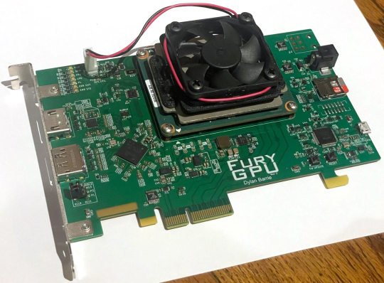
Açık kaynaklı, tamamen özel bir GPU, dört yıllık geliştirme sürecinin ardından gizlilikten çıktı. FuryGPU , bu son derece karmaşık donanım ve yazılım projesini boş zamanlarında bir araya getirdiğini söyleyen oyun yazılımı geliştiricisi Dylan Barrie'nin tek kişilik bir çabasıydı. FuryGPU, Xilinx FPGA tasarımını temel alıyor ve prototip PCIe grafik kartı şu anda Quake Timedemo'da yaklaşık 44 fps hıza ulaşma kapasitesine sahip. FuryGPU üzerindeki çalışma, Barrie'nin Ben Eater'ın sıfırdan programlanabilir 8 bit bilgisayar oluşturma projesinden ilham almasıyla gerçekleştirildi .
FuryGPU, DisplayPort ve HDMI çıkışlarıyla donatılarak modernize edilmiş, yaklaşık 20 yıl önceki tipik bir PC grafik kartına çok benziyor. Ancak proje donanımdan çok daha fazlası; Barrie, bu grafik kartının tasarımının en acı verici yönünün Windows sürücülerini oluşturmak olduğunu itiraf ediyor.
Barrie, FPGA paketli Arty Z7 geliştirme kartını alıp bazı ön geliştirme ve testler yaptıktan sonra sıfırdan bir GPU oluşturma hayallerini gerçekleştirmeye başladı. Daha sonra proje, "inanılmaz derecede ucuz Zynq UltraScale+ FPGA'leri bir ton DSP birimi ve (nispeten) büyük miktarda LUT ve FF ile birleştiren Xilinx Kria Modüller Üzerinde Sistem'in (SoM'ler) piyasaya sürülmesiyle hız kazandı. Özellikle ilgi çekici olan, güçlendirilmiş PCIe çekirdeğidir," diye heyecanla dile getirdi Barrie.
Bu üretici karttan 2024'te gördüğümüz FuryGPU PCIe eklenti kart tasarımına geçmek için Barrie, SystemVerilog donanım açıklamasını ve donanım doğrulama dilini ve KiCAD EDA / elektronik CAD yazılım paketini kendi kendine öğrendi. SoM'de yerleşik FPGA devresi olsa bile, bugün gördüğümüz 4 şeritli PCIe ile FuryGPU'nun şemasını tasarlamak için Herkül gibi bir çaba gerektiğini söylüyor. Artık FuryGPU'yu test donanımına takma, sürücüleri yazma ve oyunları test etme zamanı gelmişti.
https://www.youtube.com/watch?v=VJigQ2Rm-TQ&embeds_referring_euri=httpswww.tomshardware.com&source_ve_path=MjM4NTE&feature=emb_title
FuryGPU için Windows sürücülerini oluşturmak, Barrie tarafından tüm projenin "en acı verici" yönü olarak tanımlanıyor; günlük işi son 14 yıldır oyun geliştirme endüstrisinde grafik oluşturmanın yazılım tarafında olmasına rağmen.
Başlangıçta FuryGPU üreticisinin amacı, GPU'nun çalıştığını göstermek için basit bir dönen küp demosu oluşturmaktı. Ancak proje geliştikçe ikonik PC oyunu Quake'i oynanabilir kare hızlarında oynamak yeni hedef olmaya başladı.
Barrie, Windows sürücülerini hazırladıktan sonra, GPU ile iletişim kurmak için özel bir grafik API'si yazdığını, ekran ve ses için Windows çekirdek sürücülerini yazdığını ve artık "Quake'i istediğiniz hızda işleyebilen tam işlevli bir grafik donanımına" sahip olduğunu açıklıyor. Saniyede 60 kare.
kaynak:https://www.tomshardware.com
Read the full article
0 notes
Text
Laboratory Assignment 3 Modeling Decoders and MUXs in System Verilog
Location: EA Z04 (in the EA building, straight ahead past the elevators)
Each student should attend the time block depending on their student id. A student with student id 22050977(Odd) from section 4 should attend lab at 10:00 am on Friday for example.
Preliminary Report (30 points)
Today’s lab needs considerable advance preparation. These advance designs and SystemVerilog models should be…

View On WordPress
0 notes
Text
SystemVerilog: Tanım ve Özellikleri
SystemVerilog, donanım tanımlama dili (HDL) olarak kullanılan bir programlama dilidir. Bu dili kullanan donanım tasarımcıları, karmaşık entegre devrelerin (IC) tasarımı ve doğrulamasını gerçekleştirmek için kullanır.
SystemVerilog HDL, asenkron, senkron ve karmaşık donanım tasarımlarını gerçekleştirmek için kullanılan bir dil olarak endüstri standartlarından biridir. Bu dil, sistem seviyesi modüllerin tanımlanması, özellik tabanlı sınıflar, sınamaların şekillendirilmesi ve verilerin toplanması gibi farklı işlevleri yerine getirebilir.
SystemVerilog'in kullanımı yalnızca donanım tasarımı ve doğrulama alanlarıyla sınırlı değildir. Aynı zamanda yazılım ekipleri tarafından geliştirilen test senaryoları ve doğrulama metodları için de kullanılır.
Bu programlama dilinin, donanım ve yazılım arasındaki etkileşimi ve doğrulama süreçlerini optimize etme konusundaki yetenekleri, onu endüstride tercih edilen bir seçenek haline getirmiştir.
SystemVerilog'in Tarihçesi ve Gelişimi
SystemVerilog, Donanım Tanımlama Dili (HDL) için genel amaçlı bir programlama dili olarak kullanılır. Tarihçesi, Verilog-2005'in bir genişlemesi olarak başlar. İlk olarak Accellera tarafından geliştirilmiş ve standartlaştırılmıştır.
SystemVerilog'in gelişimi, ilk olarak 2002 yılında Accellera tarafından başlatılmıştır. Burada, öncelikle Verilog-2005'in gelişmiş versiyonları üzerinde çalışılmıştır. Bu süreçte, dilden türetilen çeşitli yazılım paketleri ve kütüphaneler geliştirilmiştir. Böylece, dili donanım tasarımı ve doğrulama konularında daha etkili ve verimli hale getirmek amaçlanmıştır.
SystemVerilog'in tarihçesindeki bir diğer dönüm noktası ise 2005 yılında IEEE tarafından yapılan standartlaştırmadır. Bu sayede, dili kullanacak olan tüm donanım tasarımcıları ve doğrulama mühendisleri için ortak bir dil ve kurallar belirlenmiş, bu sayede dilin kullanımı ve gelişimi daha da ilerlemiştir.
SystemVerilog'in gelişimi günümüzde de devam etmektedir. Yeni teknolojilere uyum sağlamak, güncel ihtiyaçları karşılamak ve endüstrideki pratik uygulamalara cevap vermek adına sürekli yeni versiyonlar ve güncellemeler yapılmaktadır.
SystemVerilog ile Donanım Tanımlama Dili (HDL) KullanımıSystemVerilog ile donanım tanımlama dili (HDL), karmaşık dijital sistemlerin tasarımı ve doğrulanması için kullanılan bir programlama dili ve donanım tanımlama dili (HDL) uzantısıdır. Bu dili kullanarak, mantıksal ve fiziksel tasarım yapıları, modüller ve entegrasyonlar yapılabilir. Bu da sistemlerin güvenilirliği, ölçeklenebilirliği ve verimliliğini artırır.Bu programlama dili, tasarım ve doğrulama sürecinde tasarımcılara yüksek seviyede kontrol ve esneklik sunar. Aynı zamanda doğrulama metodolojilerini de destekler. SystemVerilog, modern dijital tasarımın gereksinimlerini karşılayacak bir dildir.SystemVerilog ile donanım tanımlama dili (HDL) kullanımı, modern elektronik sistemlerin tasarımı ve doğrulamasında oldukça önemlidir. Bu dilin kullanılması, sistem tasarımcılarının karmaşık sistemleri daha hızlı bir şekilde tasarlamalarına ve doğrulamalarına olanak tanır. Aynı zamanda hem işlevsel doğrulama hem de formal doğrulama için geniş bir modelleme bağlamı sunar.Bu dili öğrenme ve kullanma sürecinde, katmanlı tasarım yapının avantajlarından yararlanarak, donanım tanımlama dili (HDL) kodları modüler bir şekilde oluşturulabilir ve entegre edilebilir. Bu da sistemlerin daha iyi bir yapısal organizasyon ve bakımını sağlar.SystemVerilog'de Modüller ve Tasarımların YapısıSystemVerilog, karmaşık donanımların tasarımı ve doğrulaması için kullanılan bir programlama dilidir. Modüller, SystemVerilog'de tasarımların yapısını oluşturan temel yapı taşlarıdır. Bu modüller, donanım tasarımının farklı bileşenlerini temsil eder ve genellikle birbirleriyle etkileşim içinde çalışırlar.SystemVerilog'de modüller, veri tipleri, portlar, parametreler ve fonksiyonları içerebilir. Bu özellikler sayesinde modüller, donanım tasarımında yeniden kullanılabilirlik ve modülerlik sağlar. Ayrıca,
modüler tasarımın sağladığı hiyerarşik yapı sayesinde daha karmaşık tasarımların yönetimi ve anlaşılması kolaylaşır.Modüler yapılar aynı zamanda eşzamanlı donanım tasarımı için de avantaj sağlar. Bu sayede farklı bileşenlerin aynı anda çalışabilmesi ve haberleşebilmesi mümkün olur. Bu da SystemVerilog'de modüllerin ve tasarımların yapısının önemini gösterir.SystemVerilog'de modüllerin ve tasarımların yapısının iyi anlaşılması, donanım mühendislerinin daha verimli ve sürdürülebilir tasarımlar oluşturmalarına yardımcı olur. Ayrıca, bu yapılar sayesinde donanımın doğrulanması ve test edilmesi süreci de daha etkili hale gelir.SystemVerilog Test Senaryoları ve Doğrulama MetodlarıSystemVerilog test senaryoları ve doğrulama metodları, donanım doğrulama sürecinin kritik bir parçasını oluşturur. Bu adımlar, donanımın beklenen şekilde çalıştığını doğrulamak için yazılım ve donanım mühendisleri tarafından gerçekleştirilir. SystemVerilog'in sağladığı kapsamlı test benzeri yapılar, bu süreci daha da kolaylaştırmaktadır.SystemVerilog, test senaryoları oluşturmak için geniş bir dil yapısına sahiptir. Bu dilin doğrulama metodları, eksiksiz modelleme ve simülasyon olanağı sunar. Bu sayede, donanımın karmaşıklığına uygun seviyede detaylı test senaryoları oluşturulabilir.SystemVerilog'in sağladığı assertions ve coverage özellikleri, test senaryolarının etkinliğini artırır. Assertions, belirli koşulların sağlanıp sağlanmadığını kontrol etmek için kullanılırken, coverage özellikleri ise test senaryolarının donanımın tüm bölümlerini kapsayıp kapsamadığını kontrol etmek için kullanılır.SystemVerilog ile gerçekleştirilen test senaryoları ve doğrulama metodları, donanımın güvenilirliğini artırır ve hataların erken aşamada tespit edilmesini sağlar. Bu sayede, donanımın üretim aşamasına geçmeden önce kaliteli bir şekilde doğrulanması mümkün olur.SystemVerilog'in Sektördeki Uygulama Alanları ve PopülerliğiSystemVerilog, donanım tanımlama dili (HDL) olarak kullanılan bir programlama dilidir. Bu nedenle sektörde geniş bir uygulama alanına sahiptir. Özellikle mikroçip tasarımı ve doğrulama süreçlerinde yaygın olarak kullanılmaktadır. Günümüzde üretim endüstrisinin vazgeçilmez bir parçası haline gelmiştir.SystemVerilog'in popülerliğinin artmasının nedenlerinden biri, karmaşık sistemlerin tasarımı ve doğrulaması için kullanımının kolaylığıdır. Ayrıca, bu dili kullanan uzmanların endüstrinin ihtiyaçlarına daha iyi cevap verebildiği bilinmektedir. Bu da SystemVerilog'in sektördeki popülerliğini artıran etkenlerden biridir. Ayrıca, SystemVerilog ile geliştirilen donanım tasarımlarının yüksek performanslı ve güvenilir olması, bu dilin sektördeki uygulama alanlarını genişletmektedir.SystemVerilog'in endüstriyel uygulama alanlarından biri de otomotiv endüstrisidir. Otomotiv sektöründe elektronik sistemlerin karmaşıklığının artması, bu alanda SystemVerilog'in kullanımını zorunlu hale getirmiştir. Ayrıca, tüketici elektroniği, telekomünikasyon ve savunma sanayi gibi farklı sektörlerde de SystemVerilog'in kullanımı oldukça yaygındır.Bu nedenlerden dolayı, SystemVerilog uzmanlarına olan talep her geçen gün artmakta ve dilin sektördeki uygulama alanları ve popülerliği giderek genişlemektedir. Dolayısıyla, donanım tasarımı ve doğrulama süreçlerinde yer almak isteyen mühendislerin SystemVerilog'i öğrenmeleri ve uzmanlaşmaları, kariyerlerini olumlu yönde etkileyecektir.
0 notes
Text
me, sweating profusely, being forced to choose between learning SystemVerilog + Vivado and spending two hours trying (and failing) to get minecraft modpack that lets you play as a dragon working. truly a fight that will be talked about in the coming centuries.
#you see I COULD learn to do this really cool thing over break#but I could ALSO play as dragon. if the mod would fuckign. wOR K#life with theta#my mind does not like it when thints do not work and will not give me a reason for their not working so then I get Very Stuck on it#this is good for exams and physics but bad for when I want to do something but mind says 'no. dragon mod is not working and it WAS working#but now!!!! it is not'#please lord and savior hatsune miku just let me play as dragin in minecrap. free me
0 notes
Text
Mastering Modern Verification: Innovations in UVM Register Modeling
In the ever-evolving landscape of hardware verification, the prowess of UVM (Universal Verification Methodology) register modeling has become central to achieving thorough and efficient verification. This article delves into innovative strategies that redefine conventional approaches, spanning high-level abstraction, automation, enhanced coverage and verification, performance optimization, seamless integration with verification environments, continuous integration and delivery (CI/CD), UVM register model extensions, and verification tailored for emerging technologies.
1. High-Level Abstraction and Automation: Precision at Scale
a. Scripting for Automation:
Objective: Accelerate register model creation and configuration.
Implementation: Employ the precision of Python and scripting languages to automate the generation and configuration of UVM register models, ensuring scalability and reducing manual overhead.
b. Dynamic Object Creation in SystemVerilog:
Objective: Enable dynamic generation of register models from specifications.
Implementation: Leverage SystemVerilog's dynamic object creation capabilities to translate design specifications seamlessly into adaptable UVM register models, fostering a dynamic and scalable verification environment.
c. Integration with IP-XACT:
Objective: Establish a seamless design-to-verification flow.
Implementation: Integrate UVM register models with standard formats like IP-XACT to ensure interoperability, facilitating a smooth transition from design to verification and promoting a cohesive design environment.
2. Enhanced Coverage and Verification: A Comprehensive Assurance Framework
a. Coverage Groups and Sequences:
Objective: Tailor coverage to the specifics of UVM register models.
Implementation: Create dedicated coverage groups and sequences designed to comprehensively capture and analyze UVM register model behavior, ensuring a robust verification process.
b. Random Constraint Generation:
Objective: Augment coverage through register-aware random constraint generation.
Implementation: Apply sophisticated randomization techniques systematically to explore UVM register model states, pushing the boundaries of coverage and uncovering intricate design scenarios.
c. Formal Verification Techniques:
Objective: Ensure functional correctness through formal verification.
Implementation: Embrace formal methods to rigorously verify UVM register models, providing a high level of confidence in meeting specifications and uncovering subtle functional nuances.
3. Performance Optimization: Streamlining Simulation Dynamics
a. Access and Update Methods Optimization:
Objective: Enhance simulation speed through optimized UVM register model methods.
Implementation: Fine-tune UVM register model methods to streamline operations, reducing simulation time and elevating the overall efficiency of the verification process.
b. Caching Mechanisms:
Objective: Minimize redundancy and amplify performance.
Implementation: Infuse UVM register models with caching mechanisms to optimize data retrieval, reducing access times during simulation and enhancing overall performance.
c. Hierarchical Register Models:
Objective: Efficiently manage large designs.
Implementation: Implement hierarchical structures within UVM register models to simplify management, providing an efficient solution for handling intricate designs and large-scale projects.
4. Integration with Verification Environments: Achieving Harmony and Flexibility
a. Compatibility with Various Methodologies:
Objective: Design UVM register models compatible with diverse verification methodologies.
Implementation: Craft UVM register models with adaptability, ensuring seamless integration into different verification environments such as UVM and OVM, thereby enhancing flexibility and reusability.
b. Scoreboards and Monitors:
Objective: Track and analyze UVM register activity.
Implementation: Employ scoreboards and monitors strategically to gain insights into UVM register behavior, facilitating effective debugging and analysis for a more thorough verification process.
c. Functional Coverage Integration:
Objective: Ensure comprehensive verification.
Implementation: Integrate UVM register models with functional coverage tools for a holistic approach, capturing diverse functional scenarios and guaranteeing a thorough verification process.
5. Continuous Integration and Continuous Delivery (CI/CD): Orchestrating Verification Excellence
a. Reusable Components:
Objective: Expedite verification setup.
Implementation: Architect UVM register models as reusable components, facilitating faster verification setup within CI/CD pipelines and promoting efficiency throughout the development lifecycle.
b. Version Control Systems:
Objective: Track changes and foster collaboration.
Implementation: Leverage version control systems effectively to manage changes systematically, promoting collaborative development of UVM register models with version consistency.
c. Automation in CI/CD Pipelines:
Objective: Streamline deployment and execution.
Implementation: Automate the deployment and execution of UVM register models within CI/CD pipelines, ensuring a consistent and efficient verification process with minimal manual intervention.
6. UVM Register Model Extensions: Tailoring for Innovation
a. Custom Extensions:
Objective: Address specific needs, such as error injection or power modeling.
Implementation: Foster innovation by developing custom extensions within UVM register models, tailoring the models to specific verification requirements and promoting adaptability.
b. Contributions to Open Source Libraries:
Objective: Foster collaboration and innovation.
Implementation: Actively contribute to open-source UVM register model libraries and frameworks, enriching the collective knowledge and resources available to the hardware verification community.
c. Advanced UVM Register Model Features:
Objective: Leverage sophisticated UVM register model features.
Implementation: Explore and implement advanced features within UVM register models, such as register access predictors, enhancing prediction capabilities and overall model sophistication.
7. Verification for Emerging Technologies: Preparing for the Next Wave
a. Adapting to AI/ML Accelerators and RISC-V Processors:
Objective: Tailor UVM register models for emerging technologies.
Implementation: Adapt UVM register models to verify the functionality of AI/ML accelerators, RISC-V processors, and other cutting-edge technologies, ensuring preparedness for the complexities of the next technological wave.
b. Verification for Security and Safety-Critical Systems:
Objective: Ensure robustness in critical applications.
Implementation: Utilize UVM register models for the verification of security and safety-critical systems, instilling confidence in mission-critical scenarios where reliability is paramount.
c. Hardware-Software Co-Design Verification:
Objective: Verify the synergy between hardware and software.
Implementation: Develop UVM register models specifically tailored for the verification of hardware-software co-design systems, ensuring seamless integration and functionality in the ever-evolving landscape of collaborative hardware-software designs.
Conclusion: Redefining UVM Register Modeling for the Future
In conclusion, the landscape of UVM register modeling is undergoing a paradigm shift, characterized by innovative strategies that push the boundaries of conventional practices. By embracing high-level abstraction, cutting-edge verification techniques, performance optimization, seamless integration, continuous automation, model extensions, and adaptability to emerging technologies, hardware verification engineers can redefine the future, ensuring unparalleled efficiency, robustness, and adaptability in the intricate realm of hardware verification.
0 notes
Text
SPEC ELECTRICAL ENGINEER-FPGA VERIFICATION 3149069

Job ID: 3149069
Full-time Onsite Role with Paid Relocation
Award-Winning Client - Various Locations Nationwide
Specialist Electrical Engineer - FPGA Verification
Our client, a leader in the Aerospace / Aviation / Defense industry, is currently seeking a Specialist Electrical Engineer with expertise in FPGA Verification. Join our team and contribute to the verification and testing of embedded FPGA firmware for advanced radio communication systems. This role involves collaborating in a dynamic team environment and working on exciting projects for our prestigious client.
Essential Functions:
- Undertake FPGA design verification and validation for cutting-edge electronic communication systems using SystemVerilog and UVM verification techniques.
- Develop Agents, Test sequences, Covergroups, Predictors, and Scoreboards.
- Generate randomized and directed tests to achieve comprehensive functional coverage, providing valuable feedback to the team for reaching functional coverage goals.
- Create high-level and detailed verification test plans and test benches that align with system requirements and specifications.
- Collaborate with cross-functional teams to refine and verify design requirements.
- Prepare design and implementation reviews, delivering technical briefings and status updates to internal customers.
Basic Qualifications:
- Bachelor's degree in Electrical, Computer, or Software Engineering or a related STEM field, with a minimum of 5 years of relevant experience in developing and verifying FPGA/ASIC-based embedded system solutions.
- Proficiency in Object-Oriented Programming (C++, JAVA).
- Demonstrated expertise in FPGA/ASIC verification using SystemVerilog.
- Working knowledge of UVM/OVM methodology.
- Experience with Advanced Functional Verification tools to report functional coverage.
- Strong technical writing skills and the ability to communicate technical concepts/solutions effectively.
- Highly motivated, self-starting individual who excels in team environments.
- Ability and willingness to obtain a Secret Clearance.
Preferred Additional Qualifications:
- Familiarity with Ethernet Standard and design experience related to Ethernet packet processing.
- Experience with cryptographic algorithms and cryptographic solutions for embedded communication systems.
- Proven ability to analyze and debug FPGA firmware and related hardware issues.
- Active SECRET Clearance.
Job ID: 3149069
locations : Sunrise FL Columbia MD Rochester NY Salt Lake City UT
Read the full article
0 notes
Text
Cultivating High-Quality IP-XACT Compliant UVM Register Models
In today's fast-evolving semiconductor industry, the requirement for solid and interoperable solutions has never been more significant. UVM (Universal Verification Methodology) register model generation is a crucial component of semiconductor design. For planning, verifying, and validating intricate hardware designs, these models are crucial. It is essential to develop top-notch UVM register models that adhere to IP-XACT standards in order to guarantee easy integration and interoperability. The importance of IP XACT quality in UVM register model and how it supports effective semiconductor design will be discussed in this article.
What is UVM Regmodel?
An abstract SystemVerilog model called UVM_REG represents the DUT's registers and memories. It was constructed utilizing UVM principles. The UVM Regmodel is presented in detail here.
What is IP-XACT?
An XML Schema for meta-data documenting Intellectual Property (IP) used in the development, implementation, and verification of electronic systems is described in IEEE 1685, "Standard for IP-XACT, Standard Structure for Packaging, Integrating, and Re-Using IP Within Tool-Flows," along with an Application Programming Interface (API) to give tools access to the meta-data.
UVM Register Models Overview
Let's first define UVM register models and their function in semiconductor design before going into the significance of IP-XACT quality in UVM register models.
The Universal Verification Methodology (UVM), a widely used methodology for evaluating integrated circuits, which includes UVM register models as a crucial part. These models explain how registers behave and have specific properties inside a hardware design, such as their fields, access rules, reset values, and more. Engineers are able to precisely simulate, test, and verify the functioning of a hardware design thanks to UVM register models, which act as a link between the design and verification environments.How High-quality
UVM Register Models Are Important?
It is essential to produce high-quality UVM register models for the following reasons:
Accuracy: The registers in the hardware design are faithfully modeled by high-quality UVM register models. Any inconsistencies or faults in the models could result in design mistakes that wouldn't be discovered until later stages of development, costing money in modifications.
UVM register models should effortlessly connect with a variety of verification and design tools to ensure interoperability. To avoid compatibility problems and speed up the design and verification process, it is crucial to ensure compatibility and adherence to industry standards.
Reusability: Well-designed UVM register models can be used by numerous teams and projects. By removing the need to construct new models for similar ideas, this reusability shortens development cycles and saves time and labor.
Maintainability: UVM register models must stay current as hardware designs change and are updated. It is simpler to maintain high-quality models, ensuring that they precisely reflect the current design and lowering the possibility of mistakes brought on by out-of-date models.
Wholly Integrated Solutions for the IC Development Process
Every team on your SoC or IP project will profit from the specification automation tools offered by the Agnisys IDesignSpec Suite of products. Automatic file generation from executable specifications is used by designers, verification engineers, embedded programmers, pre-silicon validation engineers, and the post-silicon lab bring-up team. Technical writers can utilize the documentation in these files directly in user manuals.
Throughout your project, the Agnisys solution is advantageous to all teams. Hand coding is replaced by the automatic generation of every file. Each updated file produced when the standard changes eliminates the need for manual updating. Every stage on your project timeline occurs early and uses a lot less priceless labor.
Products that Streamline the Development of Semiconductors
Your product teams can access a connected set of products through the Agnisys product suite, comprising a unified graphical design interface (GDI) front end and a united generation engine. In order to maximize productivity and support completely automated flows, these can be shared throughout all of your teams.
IDesignSpec GDI
IDS-Batch CLI
IDS-Verify
IDS-Validate
IDS-Integrate
IDS-IPGen
Exceptional Customer Service
High client satisfaction and timely customer service are among Agnisys' core principles. In order to respond quickly, our application engineers are situated close to where our users are. Users of our client portal have access to the most recent:
Downloads of programs
Announcements about products
Courses in product and technology
Configuring licenses and requesting temporary licenses
Issues with Agnisys' issue tracking system that are particular to customers
Newsletter, Blogs and Webinars
Trainings on various technologies
Modern semiconductor design requires the development of high-quality IP-XACT-compliant UVM register models. These models are essential for testing hardware designs and making sure they work with different EDA tools and design environments. Design teams can improve the precision, reusability, maintainability, and long-term viability of their UVM register models by following IP-XACT standards, which will ultimately result in more effective and affordable semiconductor design procedures.
Agnisys is dedicated to providing cutting-edge solutions that enable semiconductor designers to fulfill the highest standards of quality and interoperability. We understand the importance of IP-XACT quality in UVM register models. We offer the knowledge and resources to meet your requirements whether you're looking to develop, test, or integrate UVM register models that are IP-XACT compatible. For more information on how we can assist you with developing superior IP-XACT-compliant UVM register models for your semiconductor design projects, get in touch with us right away.
0 notes
Link
Digital Design: With an Introduction to the Verilog HDL, VHDL, and SystemVerilog 6th Edition, ISBN-13: 978-0134549897 [PDF eBook eTextbook] Publisher: Pearson; 6th edition (March 7, 2017) Language: English 720 pages ISBN-10: 9780134549897 ISBN-13: 978-0134549897 The speed, density, and complexity of today’s digital devices are made possible by advances in physical processing technology and digital design methodology. Aside from semiconductor technology, the design of leading-edge devices depends critically on hardware description languages (HDLs) and synthesis tools. Three public-domain languages, Verilog, VHDL, and SystemVerilog, all play a role in design flows for today’s digital devices. HDLs, together with fundamental knowledge of digital logic circuits, provide an entry point to the world of digital design for students majoring in computer science, computer engineering, and electrical engineering. In the not-too-distant past, it would be unthinkable for an electrical engineering student to graduate without having used an oscilloscope. Today, the needs of industry demand that undergraduate students become familiar with the use of at least one hardware description language. Their use of an HDL as a student will better prepare them to be productive members of a design team after they graduate. Given the presence of three HDLs in the design arena, we have expanded our presentation of HDLs in Digital Design to treat Verilog and VHDL, and to provide an introduction to SystemVerilog. Our intent is not to require students to learn three, or even two, languages, but to provide the instructor with a choice between Verilog and VHDL while teaching a systematic methodology for design, regardless of the language, and an optional introduction to SystemVerilog. Certainly, Verilog and VHDL are widely used and taught, dominate the design space, and have common underlying concepts supporting combinational and sequential logic design, and both are essential to the synthesis of high-density integrated circuits. Our text offers parallel tracks of presentation of both languages, but allows concentration on a single language. The level of treatment of Verilog and VHDL is essentially equal, without emphasizing one language over the other. A language-neutral presentation of digital design is a – common thread through the treatment of both languages. A large set of problems, which are stated in language-neutral terms, at the end of each chapter can be worked with either Verilog or VHDL. The emphasis in our presentation is on digital design, with HDLs in a supporting role. Consequently, we present only those details of Verilog, VHDL, and SystemVerilog that are needed to support our treatment of an introduction to digital design. Moreover, although we present examples using each language, we identify and segregate the treatment of topics and examples so that the instructor can choose a path of presentation for a single language—either Verilog or VHDL. Naturally, a path that emphasizes Verilog can conclude with SystemVerilog, but it can be skipped without compromising the objectives. The introduction to SystemVerilog is selective—we present only topics and examples that are extensions of Verilog, and well within the scope of an introductory treatment. To be clear, we are not advocating simultaneous presentation of the languages. The instructor can choose either Verilog/SystemVerilog or VHDL as the core language supporting an introductory course in digital design. Regardless of the language, our focus is on digital design. The language-based examples throughout the book are not just about the details of an HDL. We emphasize and demonstrate the modeling and verification of digital circuits having specified behavior. Neither Verilog or VHDL are covered in their entirety. Some details of the languages will be left to the reader’s continuing education and use of web resources. Regardless of language, our examples introduce a design methodology based on the concept of computer-aided modeling of digital systems by means of a mainstream, IEEE-standardized, hardware description language. This revision of Digital Design begins each chapter with a statement of its objectives. Problems at the end of each chapter are combined with inchapter examples, and with in-chapter Practice Exercises. Together, these encounters with the subject matter bring the student closer to achieving the stated objectives and becoming skilled in digital design. Answers are given to selected problems at the end of each chapter. A Solution Manual gives detailed solutions to all of the problems at the end of the chapters. The level of detail of the solutions is such that an instructor can use individual problems to support classroom instruction. Table of Contents: Preface 1 Digital Systems and Binary Numbers 1.1 Digital Systems 1.2 Binary Numbers 1.3 NumberBase Conversions 1.4 Octal and Hexadecimal Numbers 1.5 Complements of Numbers 1.6 Signed Binary Numbers 1.7 Binary Codes 1.8 Binary Storage and Registers 1.9 Binary Logic 2 Boolean Algebra and Logic Gates 2.1 Introduction 2.2 Basic Definitions 2.3 Axiomatic Definition of Boolean Algebra 2.4 Basic Theorems and Properties of Boolean Algebra 2.5 Boolean Functions 2.6 Canonical and Standard Forms 2.7 Other Logic Operations 2.8 Digital Logic Gates 2.9 Integrated Circuits 3 GateLevel Minimization 3.1 Introduction 3.2 The Map Method 3.3 FourVariable K-Map 3.4 ProductofSums Simplification 3.5 Don’tCare Conditions 3.6 NAND and NOR Implementation 3.7 Other TwoLevel Implementations 3.8 ExclusiveOR Function 3.9 Hardware Description Languages (HDLs) 4 Combinational Logic 4.1 Introduction 4.2 Combinational Circuits 4.3 Analysis of Combinational Circuits 4.4 Design Procedure 4.5 Binary Adder—Subtractor 4.6 Decimal Adder 4.7 Binary Multiplier 4.8 Magnitude Comparator 4.9 Decoders 4.10 Encoders 4.11 Multiplexers 4.12 HDL Models of Combinational Circuits 5 Synchronous Sequential Logic 5.1 Introduction 5.2 Sequential Circuits 5.3 Storage Elements: Latches 5.4 Storage Elements: FlipFlops 5.5 Analysis of Clocked Sequential Circuits 5.6 Synthesizable HDL Models of Sequential Circuits 5.7 State Reduction and Assignment 5.8 Design Procedure 6 Registers and Counters 6.1 Registers 6.2 Shift Registers 6.3 Ripple Counters 6.4 Synchronous Counters 6.5 Other Counters 6.6 HDL Models of Registers and Counters 7 Memory and Programmable Logic 7.1 Introduction 7.2 RandomAccess Memory 7.3 Memory Decoding 7.4 Error Detection and Correction 7.5 ReadOnly Memory 7.6 Programmable Logic Array 7.7 Programmable Array Logic 7.8 Sequential Programmable Devices 8 Design at the Register Transfer Level 8.1 Introduction 8.2 Register Transfer Level (RTL) Notation 8.3 RTL descriptions VERILOG (Edge- and Level-Sensitive Behaviors) 8.4 Algorithmic State Machines (ASMs) 8.5 Design Example (ASMD Chart) 8.6 HDL Description of Design Example 8.7 Sequential Binary Multiplier 8.8 Control Logic 8.9 HDL Description of Binary Multiplier 8.10 Design with Multiplexers 8.11 RaceFree Design (Software Race Conditions) 8.12 LatchFree Design (Why Waste Silicon?) 8.13 System Verilog–An Introduction 9 Laboratory Experiments with Standard ICs and FPGAs 9.1 Introduction to Experiments 9.2 Experiment 1: Binary and Decimal Numbers 9.3 Experiment 2: Digital Logic Gates 9.4 Experiment 3: Simplification of Boolean Functions 9.5 Experiment 4: Combinational Circuits 9.6 Experiment 5: Code Converters 9.7 Experiment 6: Design with Multiplexers 9.8 Experiment 7: Adders and Subtractors 9.9 Experiment 8: FlipFlops 9.10 Experiment 9: Sequential Circuits 9.11 Experiment 10: Counters 9.12 Experiment 11: Shift Registers 9.13 Experiment 12: Serial Addition 9.14 Experiment 13: Memory Unit 9.15 Experiment 14: Lamp Handball 9.16 Experiment 15: ClockPulse Generator 9.17 Experiment 16: Parallel Adder and Accumulator 9.18 Experiment 17: Binary Multiplier 9.19 HDL Simulation Experiments and Rapid Prototyping with FPGAs 10 Standard Graphic Symbols 10.1 RectangularShape Symbols 10.2 Qualifying Symbols 10.3 Dependency Notation 10.4 Symbols for Combinational Elements 10.5 Symbols for FlipFlops 10.6 Symbols for Registers 10.7 Symbols for Counters 10.8 Symbol for RAM Appendix Answers to Selected Problems Index M. Morris Mano is an Emeritus Professor of Computer Engineering at the California State University, Los Angeles. His notable works include the Mano Machine, i.e. a theoretical computer that contains a central processing unit, random access memory, and an input-output bus. M. Morris Mano has authored numerous books in the area of digital circuits that are known for teaching the basic concepts of digital logic circuits in a clear, accessible manner. His books for the introductory digital design course, Logic and Computer Design Fundamentals and Digital Design, continue to be two of the most widely used texts around the world. Michael Ciletti is an Emeritus Professor of Electrical and Computer Engineering at the University of Colorado, Colorado Springs. An early advocate of including HDL-based design methodology in the curriculum, he pioneered and developed the offering of several courses using Verilog, VHDL, FPGAs and standard cell based hardware implementations for design, testing, and synthesis of VLSI devices. His consulting work has ranged from processor design to providing expert witness testimony in cases involving HDLs. He has developed and presented courses for industry in The United States, Asia, and Europe. His widely-adopted textbooks have promoted the use of the now-standard Verilog HDL and encouraged adoption of HDL-based design practice in logic design and computer science curricula. Ciletti resides in Colorado Springs, CO, where he pursues a strong interest in landscape photography. What makes us different? • Instant Download • Always Competitive Pricing • 100% Privacy • FREE Sample Available • 24-7 LIVE Customer Support
0 notes
Text
An Introduction to SystemVerilog: Overview and Benefits
Are you looking to get up to speed with the basics of SystemVerilog? This introduction will provide a comprehensive overview of SystemVerilog and all its benefits. SystemVerilog is an incredibly powerful programming language and hardware description language (HDL) used for the verification, design, synthesis, emulation, and prototyping of digital circuits.
The language enables users to efficiently create intricate designs that can be tested quickly and accurately for verification purposes, as well as optimized for cost reduction when transferred into silicon.
Regardless of your previous experience level or coding expertise, this guide provides all the essentials needed to understand why so many people are drawn towards using SystemVerilog in their projects.
What is SystemVerilog?
SystemVerilog is an extension of Verilog, which was developed by Accellera to enhance the design, verification, and synthesis of digital circuits and systems. This language provides object-oriented programming features, constrained random testing, assertions, and coverage analysis. It has become a popular language for both design and verification of digital systems, due to its flexibility and functionality.
Evolution of Verilog to SystemVerilog
Verilog was enhanced to SystemVerilog to address the growing complexity of digital circuits and systems. SystemVerilog added features such as object-oriented programming, constrained random testing, assertions, and coverage analysis to improve design verification, modeling, and synthesis.
Features and capabilities of SystemVerilog
Some of the notable features and capabilities of SystemVerilog include:
Object-oriented programming (OOP) features, such as classes, objects, and inheritance, enable modular and reusable design structures.
Constrained random testing (CRT) allows designers to create random input stimulus while constraining the values to ensure proper functionality and performance.
Assertions and coverage analysis enable designers to check the correctness of their designs and ensure that they meet the desired functional and performance requirements.
Design hierarchy and interface modeling enable designers to organize and manage complex designs with multiple modules and interfaces.
Design reuse and system-on-chip (SoC) design capabilities facilitate the creation of complex designs with pre-designed components and IP blocks.
SystemVerilog also includes features for low-power design, testbench automation, and FPGA synthesis.
Advantages of SystemVerilog
Here are some advantages of SystemVerilog:
SystemVerilog code is more concise and requires fewer lines of code compared to Verilog, which can save time and reduce errors.SystemVerilog includes structures and enumerated types that provide a more scalable and efficient way to design and manage complex digital systems. Interfaces in SystemVerilog provide a higher level of abstraction and enable faster design iterations and easier reuse of IP blocks.SystemVerilog is widely supported in electronic design automation (EDA) tools, including Vivado synthesis, which makes it easy to synthesize and implement designs on FPGAs
SystemVerilog vs. Verilog
Verilog is a Hardware Description Language (HDL) used for modeling and structuring electronic systems, while SystemVerilog combines HDL and Hardware Verification Language (HVL) to facilitate modeling, designing, simulating, testing, and implementing electrical systems.
In Verilog, module-level testing is used for the testbench, while SystemVerilog utilizes class-level test benches for more advanced and efficient testing. While Verilog uses C and Fortran programming languages, SystemVerilog is a programming language that combines Verilog, VHDL, and C++. Verilog supports the datatypes Wire and Reg, whereas SystemVerilog includes enum, union, struct, string, and class datatypes, enabling more versatile modeling and verification capabilities.
In addition to the differences mentioned earlier, Verilog and SystemVerilog also differ in terms of programming paradigms and procedural blocks.
Verilog supports the structured programming paradigm, whereas SystemVerilog supports both structured and object-oriented programming paradigms, enabling more advanced and modular designs.
In Verilog, there is a single always block to implement both combinational and sequential logic. However, SystemVerilog has three procedural blocks, namely always_comb, always_ff, and always_latch, that provide more precise control over logic implementation.
Verilog is based on a hierarchical module design, while SystemVerilog is based on classes that provide more sophisticated design and verification capabilities.
Conclusion
SystemVerilog is an incredibly powerful and efficient tool for those wishing to develop digital designs quickly and reliably. Its encapsulation of VHDL and Verilog properties in one language makes it a necessary addition to any collection of digital design tools.
The interface options, including the command line, graphical user interface, as well as self-verification facilities will empower users with greater flexibility as well as a sound verification process. With such a comprehensive package, it is no surprise that SystemVerilog has become so popular in the design world.
Get ahead of the game with SystemVerilog today – we at Maven Silicon are here to help you along your learning journey! Whether you’re just starting out or already familiar with SystemVerilog, contact us today to get started on our SystemVerilog tutorial.
With us, by your side, you’ll soon be confident enough to tackle more complex projects with ease. Don't wait - take the first step now and explore what SystemVerilog can do for you!
0 notes
Link
Digital Design: With an Introduction to the Verilog HDL, VHDL, and SystemVerilog 6th Edition, ISBN-13: 978-0134549897 [PDF eBook eTextbook] Publisher: Pearson; 6th edition (March 7, 2017) Language: English 720 pages ISBN-10: 9780134549897 ISBN-13: 978-0134549897 The speed, density, and complexity of today’s digital devices are made possible by advances in physical processing technology and digital design methodology. Aside from semiconductor technology, the design of leading-edge devices depends critically on hardware description languages (HDLs) and synthesis tools. Three public-domain languages, Verilog, VHDL, and SystemVerilog, all play a role in design flows for today’s digital devices. HDLs, together with fundamental knowledge of digital logic circuits, provide an entry point to the world of digital design for students majoring in computer science, computer engineering, and electrical engineering. In the not-too-distant past, it would be unthinkable for an electrical engineering student to graduate without having used an oscilloscope. Today, the needs of industry demand that undergraduate students become familiar with the use of at least one hardware description language. Their use of an HDL as a student will better prepare them to be productive members of a design team after they graduate. Given the presence of three HDLs in the design arena, we have expanded our presentation of HDLs in Digital Design to treat Verilog and VHDL, and to provide an introduction to SystemVerilog. Our intent is not to require students to learn three, or even two, languages, but to provide the instructor with a choice between Verilog and VHDL while teaching a systematic methodology for design, regardless of the language, and an optional introduction to SystemVerilog. Certainly, Verilog and VHDL are widely used and taught, dominate the design space, and have common underlying concepts supporting combinational and sequential logic design, and both are essential to the synthesis of high-density integrated circuits. Our text offers parallel tracks of presentation of both languages, but allows concentration on a single language. The level of treatment of Verilog and VHDL is essentially equal, without emphasizing one language over the other. A language-neutral presentation of digital design is a – common thread through the treatment of both languages. A large set of problems, which are stated in language-neutral terms, at the end of each chapter can be worked with either Verilog or VHDL. The emphasis in our presentation is on digital design, with HDLs in a supporting role. Consequently, we present only those details of Verilog, VHDL, and SystemVerilog that are needed to support our treatment of an introduction to digital design. Moreover, although we present examples using each language, we identify and segregate the treatment of topics and examples so that the instructor can choose a path of presentation for a single language—either Verilog or VHDL. Naturally, a path that emphasizes Verilog can conclude with SystemVerilog, but it can be skipped without compromising the objectives. The introduction to SystemVerilog is selective—we present only topics and examples that are extensions of Verilog, and well within the scope of an introductory treatment. To be clear, we are not advocating simultaneous presentation of the languages. The instructor can choose either Verilog/SystemVerilog or VHDL as the core language supporting an introductory course in digital design. Regardless of the language, our focus is on digital design. The language-based examples throughout the book are not just about the details of an HDL. We emphasize and demonstrate the modeling and verification of digital circuits having specified behavior. Neither Verilog or VHDL are covered in their entirety. Some details of the languages will be left to the reader’s continuing education and use of web resources. Regardless of language, our examples introduce a design methodology based on the concept of computer-aided modeling of digital systems by means of a mainstream, IEEE-standardized, hardware description language. This revision of Digital Design begins each chapter with a statement of its objectives. Problems at the end of each chapter are combined with inchapter examples, and with in-chapter Practice Exercises. Together, these encounters with the subject matter bring the student closer to achieving the stated objectives and becoming skilled in digital design. Answers are given to selected problems at the end of each chapter. A Solution Manual gives detailed solutions to all of the problems at the end of the chapters. The level of detail of the solutions is such that an instructor can use individual problems to support classroom instruction. Table of Contents: Preface 1 Digital Systems and Binary Numbers 1.1 Digital Systems 1.2 Binary Numbers 1.3 NumberBase Conversions 1.4 Octal and Hexadecimal Numbers 1.5 Complements of Numbers 1.6 Signed Binary Numbers 1.7 Binary Codes 1.8 Binary Storage and Registers 1.9 Binary Logic 2 Boolean Algebra and Logic Gates 2.1 Introduction 2.2 Basic Definitions 2.3 Axiomatic Definition of Boolean Algebra 2.4 Basic Theorems and Properties of Boolean Algebra 2.5 Boolean Functions 2.6 Canonical and Standard Forms 2.7 Other Logic Operations 2.8 Digital Logic Gates 2.9 Integrated Circuits 3 GateLevel Minimization 3.1 Introduction 3.2 The Map Method 3.3 FourVariable K-Map 3.4 ProductofSums Simplification 3.5 Don’tCare Conditions 3.6 NAND and NOR Implementation 3.7 Other TwoLevel Implementations 3.8 ExclusiveOR Function 3.9 Hardware Description Languages (HDLs) 4 Combinational Logic 4.1 Introduction 4.2 Combinational Circuits 4.3 Analysis of Combinational Circuits 4.4 Design Procedure 4.5 Binary Adder—Subtractor 4.6 Decimal Adder 4.7 Binary Multiplier 4.8 Magnitude Comparator 4.9 Decoders 4.10 Encoders 4.11 Multiplexers 4.12 HDL Models of Combinational Circuits 5 Synchronous Sequential Logic 5.1 Introduction 5.2 Sequential Circuits 5.3 Storage Elements: Latches 5.4 Storage Elements: FlipFlops 5.5 Analysis of Clocked Sequential Circuits 5.6 Synthesizable HDL Models of Sequential Circuits 5.7 State Reduction and Assignment 5.8 Design Procedure 6 Registers and Counters 6.1 Registers 6.2 Shift Registers 6.3 Ripple Counters 6.4 Synchronous Counters 6.5 Other Counters 6.6 HDL Models of Registers and Counters 7 Memory and Programmable Logic 7.1 Introduction 7.2 RandomAccess Memory 7.3 Memory Decoding 7.4 Error Detection and Correction 7.5 ReadOnly Memory 7.6 Programmable Logic Array 7.7 Programmable Array Logic 7.8 Sequential Programmable Devices 8 Design at the Register Transfer Level 8.1 Introduction 8.2 Register Transfer Level (RTL) Notation 8.3 RTL descriptions VERILOG (Edge- and Level-Sensitive Behaviors) 8.4 Algorithmic State Machines (ASMs) 8.5 Design Example (ASMD Chart) 8.6 HDL Description of Design Example 8.7 Sequential Binary Multiplier 8.8 Control Logic 8.9 HDL Description of Binary Multiplier 8.10 Design with Multiplexers 8.11 RaceFree Design (Software Race Conditions) 8.12 LatchFree Design (Why Waste Silicon?) 8.13 System Verilog–An Introduction 9 Laboratory Experiments with Standard ICs and FPGAs 9.1 Introduction to Experiments 9.2 Experiment 1: Binary and Decimal Numbers 9.3 Experiment 2: Digital Logic Gates 9.4 Experiment 3: Simplification of Boolean Functions 9.5 Experiment 4: Combinational Circuits 9.6 Experiment 5: Code Converters 9.7 Experiment 6: Design with Multiplexers 9.8 Experiment 7: Adders and Subtractors 9.9 Experiment 8: FlipFlops 9.10 Experiment 9: Sequential Circuits 9.11 Experiment 10: Counters 9.12 Experiment 11: Shift Registers 9.13 Experiment 12: Serial Addition 9.14 Experiment 13: Memory Unit 9.15 Experiment 14: Lamp Handball 9.16 Experiment 15: ClockPulse Generator 9.17 Experiment 16: Parallel Adder and Accumulator 9.18 Experiment 17: Binary Multiplier 9.19 HDL Simulation Experiments and Rapid Prototyping with FPGAs 10 Standard Graphic Symbols 10.1 RectangularShape Symbols 10.2 Qualifying Symbols 10.3 Dependency Notation 10.4 Symbols for Combinational Elements 10.5 Symbols for FlipFlops 10.6 Symbols for Registers 10.7 Symbols for Counters 10.8 Symbol for RAM Appendix Answers to Selected Problems Index M. Morris Mano is an Emeritus Professor of Computer Engineering at the California State University, Los Angeles. His notable works include the Mano Machine, i.e. a theoretical computer that contains a central processing unit, random access memory, and an input-output bus. M. Morris Mano has authored numerous books in the area of digital circuits that are known for teaching the basic concepts of digital logic circuits in a clear, accessible manner. His books for the introductory digital design course, Logic and Computer Design Fundamentals and Digital Design, continue to be two of the most widely used texts around the world. Michael Ciletti is an Emeritus Professor of Electrical and Computer Engineering at the University of Colorado, Colorado Springs. An early advocate of including HDL-based design methodology in the curriculum, he pioneered and developed the offering of several courses using Verilog, VHDL, FPGAs and standard cell based hardware implementations for design, testing, and synthesis of VLSI devices. His consulting work has ranged from processor design to providing expert witness testimony in cases involving HDLs. He has developed and presented courses for industry in The United States, Asia, and Europe. His widely-adopted textbooks have promoted the use of the now-standard Verilog HDL and encouraged adoption of HDL-based design practice in logic design and computer science curricula. Ciletti resides in Colorado Springs, CO, where he pursues a strong interest in landscape photography. What makes us different? • Instant Download • Always Competitive Pricing • 100% Privacy • FREE Sample Available • 24-7 LIVE Customer Support
0 notes
Last Seen Blogs

zhitomir
ЖЖ инфо

saintkaylaa
𐐪 𝚔𝚊𝚢𝚕𝚊 𐑂

hey-im-veronica-blog
hey, i'm veronica!

shaun-the-sheep-fanblog
Shaun the Sheep

i-can-bench-220
it’s trappin’ time!