fishboytech
Fishboy Tech
Notes from the tech bench, the studio, and the stage.
85 posts
Don't wanna be here? Send us removal request.
Last Seen Blogs

kookie-culture
spring day

americanjews
American Jews

diiascia
月

jizzie
sadie!

12-days-of-rexsoka
12 Days of Rexsoka
Note
Hello! I recently bought the Ibanez echo shifter es3 & I am really happy with it! ~ however there is still no option for completely killing the dry signal. Upon research I came across your mod from a couple of years ago that achieves exactly that on the es2, so now I wanted to ask you if you have any experience with the newer version or how you figured out the circuit board & how you ‘read’ from which resistor exactly the dry signal gets mixed into the main output? I don’t have much experience with reading smd & I don’t want to damage my pedal :/ I would appreciate any advice, thanks in advance :))
Hey, thanks for the question. First, I’ll say I don’t have any experience with the newer ES3 pedal.
To find where the dry signal is, I would start by looking near the output jack. There will probably be a TL072 chip (as you can see in one of the pics in my post about the mod, which I’ll paste below), or maybe another dual opamp chip, which is acting as an output summing amp (summing the wet and dry signals to create the output of the pedal). Look for a pair of SMD resistors of the same value near there, one that carries the wet signal to the summing pin of the opamp, and the other that carries the dry signal to the summing pin of the opamp.
https://fishboytech.tumblr.com/post/82239949806/ibanez-es2-100-wet-mod
To “read” which signal is appearing at a given circuit board node, you want an audio probe with a high impedance input. For example, I use this Audio Sniffer I built from a kit (which is unfortunately not available):
http://www.openmusiclabs.com/store1/audio-sniffer-store/index.html
If you search for "Audio Probe Tester” you’ll find some DIY projects to build something similar. It will let you listen to what’s happening at each node of the circuit. It’ll take some exploration, but with patience you should be able to find the pre-summing dry signal node that you want.
TIP: Make sure, when you’re grounding one end of the summing resistor, that you ground the end that’s AWAY from the summing opamp... otherwise, you’ll be grounding out the wet signal too!
4 notes
·
View notes
Link
9VAC Power Supplies are strangely hard to come by, and expensive... here's how to convert a 12VDC supply to a 9VAC, just by taking out some parts...
1 note
·
View note
Photo
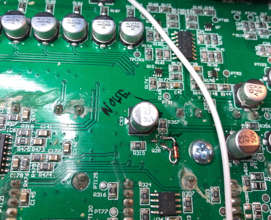
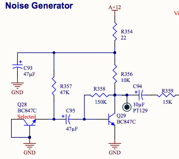
Fixed the crackly, grainy noise on my Minibrute by pulling out Q28 and replacing it with a 10V Zener diode.
1 note
·
View note
Audio
Three short Arturia Minibrute noise samples in sequence. The first is pulled from a 2015 recording, when the synth was new. The next two are from 2019, and were taken using an audio probe applied directly to the circuit board.
2015 output
Noise from the output of synth (there was some amplitude modulation used in this patch, so it’s not “pure” noise)
2019 Q28
Noise from the emitter of Q28. Once recorded, this was gained up in the computer by 28 dB, in order to have a similar loudness as the other samples. An oscilloscope reading shows the amplitude of noise at this circuit node to be about 40mVpp.
2019 Q29
Noise from the collector of Q29. The scope shows this amplitude to be about 1Vpp. Since the circuit inverts the signal polarity, the recording was polarity flipped “back” in the computer, to make it easier to visually compare to the 2019 Q28 sample. As you can hear, the already somewhat grainier texture of the Q28 noise source becomes very spitty and crackly after the Q29 gain stage.
Schematic
0 notes
Photo

A hi-resolution shot of the Erebus mod, circuit board wiring points.
0 notes
Text
Dreadbox Erebus mods
A couple years back, I was working on a “breakout box” for the Dreadbox Erebus tabletop synth. I put “breakout box” in quotes, because in addition to tapping into handful of signal and control points in the Erebus circuit, this project included a bunch of extra utility functions (noise generator, sample & hold, ring modulator, extra LFO, etc etc). I was never totally happy with the mechanical solutions I came up with for attaching the breakout box, and the density of its front panel was going to make wired connections to all the jacks and pots kind of a mess (and I don’t have the PCB design skills to create a control board for the jacks and pots to connect directly to). Eventually I got a Eurorack case and started getting into that world, so I no longer felt I needed to cram all those extra synth circuits into an add-on box for the Erebus, since I could just patch in Eurorack modules instead.
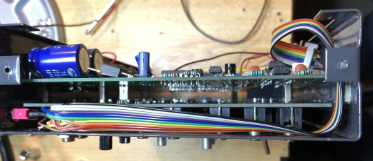
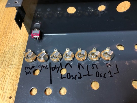
Eventually I looped back around to seeing if I could just add a few extra i/o points to the Erebus, and found that I could squeeze in open-frame Switchcraft jacks between the front panel and the first PCB down from that:

It doesn’t leave much extra room, but it doesn’t actually touch the PCB, so nothing is being stressed or bent.
It doesn’t leave much extra room, but the jacks don’t actually touch the PCB, so nothing is being stressed or bent. That, combined with the available, unused space behind the “Erebus - Analog Synthesizer” graphics, in the top right corner of the front panel, would allow for enough space to add some new onboard jacks. With that question settled, I was off and running.
Next issue was figuring out which mods to include. Direct outputs from the 2 oscillators was top on my list, with each waveform available on its own jack - so that’s 4 jacks right there.
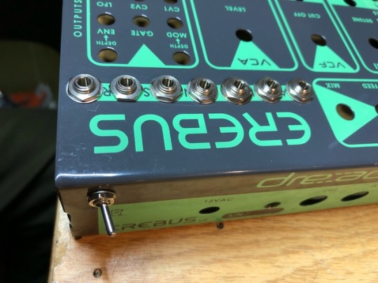
I also wanted to add an oscillator sync input to osc #2, and I wanted to provide another external signal input on the front panel (there is one already on the top panel, but it’s a 1/4” jack and not in the easiest place to access when doing Eurorack patches). The onboard delay could easily be tapped for a 100% wet echo output, so that went on the list.

Lastly, I wanted to add a switch to hold the gate open when using the Erebus in a patching situation. The same thing could be accomplished by externally patching 5V to the Erebus gate input, but I was doing this so often that I thought I’d reduce the clutter of the patching setup while I was in there modding things. There’s a 5V regulator onboard the Erebus, so I tapped the voltage I needed for the gate from that (going through a 1k resistor to limit current draw).

Here’s another detail photo of how I did the wiring inside - using a 10-pin ribbon cable to keep things neat:
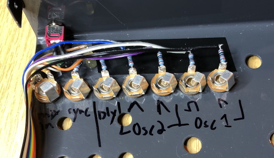
Note that the external mix input (leftmost in the photo) uses a switching jack, so that the input normals to ground if nothing is plugged in. This is to prevent noise being picked up on an open wire. You can also see a dab of hot glue in that photo, to anchor that cap/resistor combo that’s hanging off the sync input jack. And there’s also electrical tape as insulation – in case one of those flying resistor ends gets bent against the metal chassis, that will prevent it from shorting out.
At the other end of that ribbon cable (after snaking around to the back side of the circuit boards), the cable’s connector mates with a 10-pin header. That header is the point to which free-flying wires connect to the various points on the circuit board. Here, a picture is worth 10,000 words…
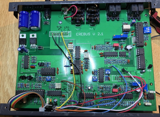
Since this photo gets pretty crunched down in this text post, I’m also posting it as a photo post here, so you can see it in high resolution.
(You can also see an extra 3.5mm jack in this shot, next to the regular output jack at the top. It’s just a mult of the regular output, and it’s not part of this mod.)
In case you haven’t caught on yet, this project is not for beginners. It requires a full disassembly of the Erebus, including removing both circuit boards – which in turn requires removing 40-some nuts for all the jacks, knobs, and switches. (If you do this, get a sorting tray of some kind! Even though you can use the same socket wrench for the switch and the jack nuts, they have different threading, and are not interchangable.) And it requires a steady hand to tack wires into some delicate spaces, confidence in using a multimeter and scope to do signal tracing, and enough experience to improvise your way around the ad hoc construction.
Anyways, I’m not writing out a full step-by-step set of instructions for this. But if you decide to attempt modding your Erebus in this way, here is a list of parts that you may find useful…
Parts
6 x mono 3.5mm Switchcraft jacks
1 x mono 3.5mm switching Switchcraft jack
1 x sub mini toggle switch, SPST
1 x 10 wire flat ribbon cable, rainbow colored, 12” length
1 x 10 pin header, male
7 x 1k resistors
1 x 220k resistor (for the mix input)
1 x 1nF capacitor (for the sync input)
wire (stranded wire 24-30 ga recommended)
0 notes
Photo


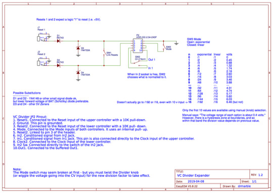
Expander Module for the SSSR VC Divider.
I built the VC Divider last year, and I have since found a lot of use for it in generative synth patches, to divide clock and trigger signals down. It has an onboard 10-pin header that can be used to configure some options by using jumpers. But it was also well-documented so that I could create an expander module to make all those options readily available.
After designing the expander circuit, I built it onto a 3hp panel. (In case you’re wondering, it may have been possible to squeeze it onto a 2hp, but the top toggle switch might not have had enough space then for the adjacent ribbon cable header that protrudes somewhat behind the expander panel.) The circuit is passive, so no power connector is needed.
I highly recommend using a rainbow ribbon cable for this project - the color coding makes it so much easier to keep track of the wires.
Don’t forget the ground connection to the local ground (I did at first!). The expansion jumper has ground on pin 2 (here, the red wire of the rainbow ribbon cable). So I ran a small jumper wire from the toggle’s top lug to the “sleeve” lug of the closer jack. It’ll still work without that wire in place, but you want to ensure that the input protection diodes (D3 and D4) have a path to ground no matter what.
Oh, and labeling was done with a Brother P-touch labelmaker, using 6mm black-on-clear tape. I kept the labels long so I could wrap them around the sides, just makes it look a little neater.
1 note
·
View note
Note
Hi, thanks very much for your precision adder layout, just the thing I'd like to use with the Korg SQ 1 and 0 coast. I cannot find the schematic though on your page, do you have it please? I can only see the stripboard image from fritzing. Perhaps you could post the schematic and the .fzz file? That would be awesome! Thanks again, all the best for the new year! Regards, Robin
Hey, thanks for the note! That is weird, I swore I had posted the schematic as well before. I will amend that post about the precision adder by adding the schematic image.I agree that the Fuzzmeasure (.fzz) file would be useful as well - just not sure if I can post arbitrary file types to Tumblr. Might have to choose an off-site sharing solution for that.Oh, and one thing I would change now about the schematic – despite what my note on there says, I would definitely generate the 5v (for normalling to input C) onboard, rather than use the 5v line from the power supply. The reason, as I discovered, is that even with a high quality power supply (Doepfer), the 5v line is somewhat dirty with power supply switching noise. Apparently, the 5v line is primarily intended to power digital circuitry, so piping it directly into a pathway that might be used for audio, and subsequently passed through high gain stages, can expose that noise.
0 notes
Photo

Erebus mods, wiring harness complete.
0 notes
Photo

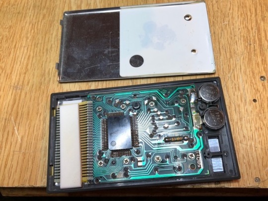
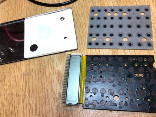

Fixed my roughly 30-year-old calculator this morning. This thing has run on the same set of batteries forever. But it had recently become unresponsive to any keypresses. It would just display a zero, and wouldn’t do anything, even turn off, in response to pressing the keys. So I opened it up and changed the batteries, but this unfortunately did not fix it. Crossing my fingers, I delved in another level, removing the eight tiny screws that hold the circuitboard to the front face of the calculator. There, as you can see in picture number three, was a grid of contact switch pads. I got out some electronic cleaner, sprayed the board down, and wiped it with a Q-tip. Also used a Q-tip with cleaner on it to swab each of the contact points on the rubber membrane. When the parts were reassembled, low and behold, it worked! Some people might wonder, why bother? Well, for one, I have a nostalgic attachment to this particular calculator, having used it since way back in middle school. I also find it handy to have a calculator to leave out on the electronics bench, so I don’t have to pull out my damn phone every time I need to run some quick numbers for Ohm’s law or whatnot. Lastly, I fix things because I can, since the alternative would be just creating more landfill.
0 notes
Photo

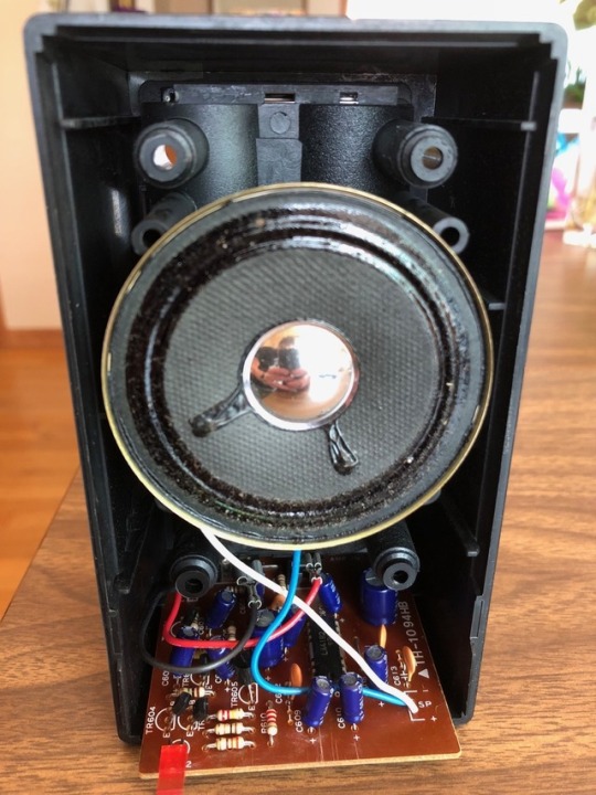
Monitor controller, new guts.
The aforementioned Electronics-Salon relay switching board (at center, with the blue relays) has replaced a mechanical rotary switch for output routing. There are now 4 separate outs (each of them stereo & balanced):
Mains
Mono sum to Avantone
Small speakers
Headphone amp
In the pic, the mono sum output is the rightmost of the 4 output jacks. Left and right channels are summed through pairs of 12k resistors hanging off the jack (both + and - sides of the balanced signal are summed).
Still rocking a Dantimax RelVol3 for the stepped relay attenuation.
New mute switch toggle in front simply cuts power to the output relay board, thereby closing all the relays.
The Electronics-Salon board required at least 8 volts, while the Dantimax attenuator and control boards still need 5 volts. So I re-did the power supply (small vertical protoboard on the right) with an external 9V wall wart, passed through a polarity protection diode (which drops the voltage to ~8.4 V) to the Electronics-Salon board. That power is also split off to an MC78M05 voltage regulator, which creates the 5 V for the Dantimax boards.
That voltage regulator needs to drop the voltage from 8.4 to 5 volts, and the attenuator board can suck down up to 400mA (the current draw varies depending on the attenuator setting, because that controls how many relays are switched on). That’s means it needs to handle dissipating up to 1.36 watts (3.4 V * 0.4 A)! It was getting quite warm when left in those heavy current draw positions, and calculations for thermal performance showed it would be pushing its maximum temperature if simply left as-is. So I added a big heatsink to it, which in the photo is covering over the voltage regulator.
0 notes
Photo

Added flyback diodes to the Electronics-Salon Balanced Four Stereo Audio Signal Input Selector Relay Module. Why they omitted them in the first place, I don’t know.
I will be replacing the old mechanical rotary switches in my monitor controller with these boards, after one of the switches snapped off in use (after many years of service).
1 note
·
View note