#orthometric
Text
Stepbro Ramming his Horny Blonde sister brother and sister having sex
American naked massage
Jane Wilde manipulated the couple Derrick Pierce and Dee Williams to hard threesome fucking
Legal age teenager slim honey spreads legs and stimulates juicy pussy
Steamy big cock doggy action for luscious teen hottie
White teen dp and fun russian anal Home Away From Home Away From Home
Lesbea Horny blonde Cristal Caitlin 69 fun with big tits Tindra Frost
Family Sex Games From Israeli Movie
Hentai doctor gets fucked by many tentacles
Paja ecuador
#Sabino#drive-#Notkerian#sunfoil#McNamara#all-red#trilemma#auntish#unfactorable#orthometric#husbanded#gaea#ferritungstite#Pro-syrian#vaccination#unrespited#Tonie#Chretien#overdevoutness#Hong-Kong
0 notes
Text
What is CAD and AutoCAD?
CAD
Before a product is ever made, it is possible to digitally develop 2D drawings and 3D models of it using computer-aided design. By making designs simple to share, review, simulate, and edit using 3D CAD, you can quickly bring new, unique items to market.
Dr. Samuel Geisberg founded Parametric Technology Corporation (PTC) in 1985 and came up with a completely fresh method for CAD software. This breakthrough led to the creation of the first parametric and feature-based solid modelling CAD software, which is now known as Creo and is the de facto industry standard for software used in product design and development.
After more than 30 years, the product development business is starting to follow the lead of so many other sectors in embracing the next wave of technology-driven innovation.
Types of CAD software
Contrary to AutoCAD, which is intended for professional usage, other CAD applications like Sketch up Pro and Turbo CAD Deluxe are targeted at average users who need some of AutoCAD's features but don't want to incur its expensive cost or steep learning curve. Additionally, although some CAD programmes can only create 2-D or 3-D drawings or models, AutoCAD can do both.
AutoCAD
Modelling of structures, manufactured items, urban infrastructure, and even fashion design are all done with the use of AutoCAD, a trademarked product of Autodesk. These ideas are created using digital 2-D or 3-D models, and the software provides users with a number of design options to help them create their blueprints.
There are many versions of the AutoCAD software for various task kinds, such as architecture, mapping, and piping design, because different fields use AutoCAD in different ways.
AutoCAD software can be used to make 2- and 3-dimensional drafts of custom house designs or renovations if you are an architect or designer. If you are a civil engineer, you can utilise AutoCAD software to plan road improvements and create more energy-efficient cities and towns. Manufacturing, automotive technology, and engineering are some other fields and professions that use CAD and AutoCAD software.
Although bitmap graphics can also be input, AutoCAD works in layers with vector images, which immediately brings to mind programmes in the mould of Photoshop or Illustrator.
However, its complete interface is separated as follows and is created for the design of plans and structures:
Where we will create our designs is the graphic area.
Options Ribbon: This is where we'll list the most frequent behaviours in our office setting.
Toolboxes and a drop-down menu
The status bar contains information in vector form about coordinates, grid control buttons, and orthometric mode, among other things.
Command line, used to communicate with the software through instructions to obtain computations or data that AutoCAD automatically gathers and that we may need
What Separates CAD from AutoCAD
Let's examine how CAD and AutoCAD differ from one another. We'll talk about the many kinds of CAD software and even the prospects for employment for CAD operators.
The general phrase "computer-aided design" (CAD) refers to the use of software and computer tools to produce 2-D and 3-D technical drawings. Geometric shapes are created and manipulated using CAD software in general to generate specific designs. The word AutoCAD refers to a proprietary programme of the same purpose developed by Autodesk, Inc. in 1982. In addition to being utilised in all stages of design for manufacturing, infrastructure, and building construction, AutoCAD software is also used to produce 3-D visual effects in the media and entertainment industry.
Important Information Regarding CAD
Average Salary (2018)
Mechanical engineers charge $87,370, interior designers charge $53,370, and so forth (drafters)
Basic Skills
Knowledge of CAD software, technical drawing abilities, and expertise in engineering, manufacturing, architecture, and design
Environment at Work
A work environment, a building site, or another outdoor location
Professional Licensure
Autodesk-sponsored courses and tests offer a variety of certification levels, including AutoCAD Certified User, AutoCAD Certified Associate, and AutoCAD Certified Professional.

Feel free to contact Cadd centre Nagpur. We offer training for CAD/CAM/CAE, Mechanical CAD courses, Civil, Electrical and Architecture Design & Analysis courses. Get the skilled in right away and get right job.
Call us on 7507111164, 7507111145
0 notes
Photo

O Instituto Marden Bastos recebeu a visita ilustre do Diretor da @orthometric @roquemeridajr e do Diretor comercial da marca @fabiosesti1 .👏🏻 Os representantes da @orthometric ficaram encantados com o trabalho desenvolvido pelo nosso Instituto. 🙏🏻 Em breve muitas novidades para nossos alunos. Aguardem 💥 ⠀ ⠀ ⠀ ⠀ ⠀ ⠀ ⠀ ⠀ ⠀ ⠀ ⠀ ⠀ ⠀ ⠀ ⠀ ⠀ ⠀ ⠀ ⠀ ⠀ ⠀ ⠀ ⠀ ⠀ ⠀ ⠀ ⠀ ⠀ ⠀ ⠀ ⠀ ⠀ ⠀ ⠀ ⠀ ⠀ ⠀ ⠀ ⠀ ⠀ ⠀ ⠀ ⠀ ⠀ ⠀ ⠀ ⠀ ⠀ ⠀ ⠀ ⠀ ⠀ ⠀ ⠀ ⠀ ⠀ ⠀ ⠀ ⠀ ⠀ ⠀ ⠀ ⠀ ⠀ ⠀ ⠀ ⠀ ⠀ ⠀ ⠀ ⠀ ⠀ ⠀ ⠀ ⠀ ⠀ ⠀ ⠀ ⠀ ⠀ ⠀ ⠀ ⠀ ⠀ ⠀ ⠀ ⠀ ⠀ ⠀ ⠀ ⠀ ⠀ ⠀ ⠀ ⠀ ⠀ ⠀ ⠀ ⠀ ⠀ ⠀ ⠀ ⠀ ⠀ ⠀ ⠀ ⠀ ⠀ ⠀ ⠀ ⠀ ⠀ ⠀ ⠀ ⠀ ⠀ ⠀ ⠀ ⠀ ⠀ ⠀ ⠀ ⠀ ⠀ ⠀ ⠀ ⠀ ⠀ ⠀ ⠀ ⠀ ⠀ ⠀ ⠀ ⠀ ⠀ ⠀ ⠀ ⠀ ⠀ ⠀ ⠀ ⠀ ⠀ ⠀ ⠀ ⠀ ⠀ ⠀ ⠀ ⠀ ⠀ ⠀ ⠀ ⠀ ⠀ ⠀ ⠀ ⠀ ⠀ ⠀ ⠀ ⠀ ⠀ ⠀ ⠀ ⠀ ⠀ ⠀ ⠀ ⠀ ⠀ ⠀ ⠀ ⠀ #orthometric #institutomardenbastos #escolaespecializada #alfenasmg #ortodontiadigital #ortodontics (em Instituto Marden Bastos) https://www.instagram.com/p/CKpcGVypAon/?igshid=a8kfyqt915to
0 notes
Link

Indian news media outlets have cited unnamed ‘senior military officers’ as saying that the Indian Air Force used the Israeli SPICE 2000 weapon to target four buildings at a terrorist camp in Balakot. The SPICE 2000 is the Israeli analogue of the US JDAM (joint direct attack munition), the weapon that has become the mainstay of coalition airstrikes in the Middle East. The SPICE 2000 is essentially a strap-on guidance kit that can transform a 2,000-pound ‘dumb’ bomb into a very precise way to deliver more than 400 kilograms of high explosives at a range of up to 60 kilometres. The weapon can be both GPS- and electro-optically guided. A 2,000-pound bomb causes substantial damage to structures. ...
The strike could have relied on the SPICE 2000’s electro-optical guidance capabilities, but that would have required significant targeting support, including the development of topographically and architecturally precise modelling to program and guide the weapon. It is not a simple process and is dependent on considerable pre-strike imagery-collection and targeting infrastructure. It is likely that the Indian Air Force opted instead to rely solely on the weapon’s ‘set and forget’ GPS capabilities.
It is important to note two characteristics of GPS-guided weapons. The first is that GPS coordinates have three dimensions: elevation, latitude and longitude—something we tend to overlook in everyday life when we navigate using a mobile phone’s GPS function. Second, a glide weapon like the SPICE 2000 doesn’t fall vertically to its target; it follows an inclined trajectory. Therefore, an incorrect vertical coordinate will result in the weapon missing as surely as an error in latitude or longitude.
Such errors can occur for various reasons, including by neglecting to convert coordinates from one coordinate system, or datum, to another (a datum shift). One potential candidate in this case is the difference between GPS ellipsoidal height and orthometric height based on mean sea level (see here for an explanation). In northeastern Pakistan, the difference is around 33 metres, although in many areas the difference is not precisely mapped so it may be larger or smaller at a point such as Balakot.
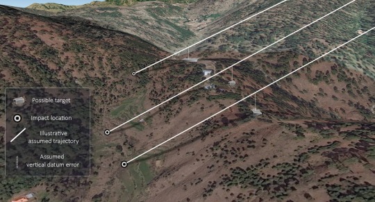
One explanation for the miss is that the SPICE 2000 bombs were incorrectly programmed to fly precisely into GPS points that were, say, 33 metres above their intended targets (the buildings on top of the ridge line). They performed as programmed and then continued on their trajectories until they struck the valley beneath.
The image below correlates the identified impact sites, the buildings that were the likely targets and a discrepancy between ellipsoidal and orthometric height which we have assumed to equate to 33 metres above the target buildings. Presented in 3D, this correlation results in consistent, parallel trajectories indicating a consistent targeting error. The differences in the impact distances from the intended targets are accounted for by the steep terrain and the differences in elevation between the impact sites. While this diagram does not necessarily represent the actual trajectories of the missiles, it does suggest a systematic targeting error caused by the use of different vertical datums.
60 notes
·
View notes
Photo

Por mais que aparenta ser brincadeira, por trás disso tudo tem muito trabalho e seriedade!!! SOMOS FELIZES EM FAZER PARTE DESSA HISTÓRIA... / #UniversoCasuo #MarcosCasuo #Orthometric #eventos (em Quality Sun Valley)
0 notes
Text
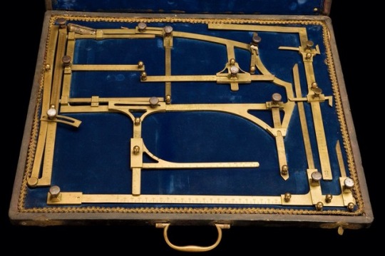
Orthometre brass eye measuring instrument in velvet lined wooden case, 1895. Designed by Alphonse Bertillon in Paris, France as a criminal identification tool.
The protrusion or retraction of the eyeballs is measured by an Orthometre. It was designed by French criminologist Alphonse Bertillon (1853–1914) for his ‘anthropometrics’ system. This recorded detailed physical measurements to identify individuals. Bertillon used various tools to measure height, head circumference, arm length, leg length, finger lengths and eyeball protrusion. His system was used to identify suspects in criminal cases. The system was extremely popular in France, leading to many convictions. It was superseded by more accurate and less labour-intensive fingerprinting. Bertillon pioneered many modern forensics techniques such as the ‘mug shot’, which is the standardised photography of criminals. U.K. Science Museum
11 notes
·
View notes
Text
Geoid Modelling for Surveying Works Using Satellite Geo-Spatial Data- Juniper Publishers
Introduction
Nowadays fully three-dimensional positions - latitude, longitude and height are commonly provided by Global Positioning Systems (GPS) with WGS84 ellipsoid as a reference surface. The knowledge of terrain heights is very essential for several surveying and civil engineering works. The type of heights needed for such applications is a height above mean sea level (MSL), usually called orthometric height. A precise geoid model is required to transform GPS-based geodetic heights to orthometric height to allow such data to be directly used in surveying and civil engineering applications [1]. The process of geoid modelling can only be performed if dense networks of precise levelling or gravity and astronomical deflections of vertical are made available.
Go to
Objective
The objective of this article is to formulate a local geoid model that would allow utilization of GNSS data in the fields of surveying and civil engineering in Riyadh city, capital of Saudi Arabia.
Go to
Literature Review
Several regional or local geoid models have been developed, such as: Kamguia, et al [2] (Cameroon); Merry [3] (South Africa); Aleem KF [4] (Port Harcourt, Nigeria); Dawod & Hosny [5] (Egypt); Manandhar & Shanker [6] (Nepal); Younis [1] & [7] (Palestine). Developed and tested geoid models include: Milbert & Smith [8], developed a GEOID96 model for the United States and when testing 2729 GPS points on leveled benchmarks found a RMS error of 5.8cm with no offsets or trends removed. Zhan-Ji [9] showed that a geometric geoid model developed for Hong Kong would provide an accuracy of 3 cm and a relative geoid height difference less than 1 ppm for a base line longer than 30 km. Zan-Ji [10] constructed the Hong Kong gravimetric geoid with an accuracy of about 2 cm when compared with geoid heights of 31 check points derived from GPS/Leveling data. Lin 11], generated two geometric geoid models and one gravimetric-geometric geoid model for Tainan City using the GPS and leveling data. He used fifth- and seventh-degree polynomial, and achieved orthometric height accuracy of 2-4 cm.
Eteje [12] formed a geoid model using eight benchmarks. To interpolate geoid heights of new points, they used bi-cubic geoid model and obtained an accuracy of ± 1.7cm. Younis (7) constructed a geoid model for Palestine using finite element method. Using 2nd and 3rd order polynomial, the accuracy of 1-3 cm have been achieved. Kamguia, et al [2], formed a geometric geoid model for a small area in Cameroon and obtained an accuracy of 14 cm. After a four-parameter fitting to the GPS/levelled data, the accuracy reduced to 11 cm.
Go to
Geoid Modelling
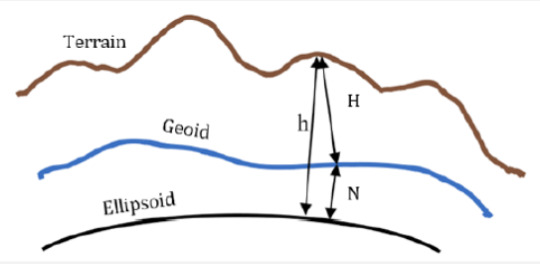
There are two approaches for developing a geoid model: geometric and gravimetric approaches. Geometric is the one most applicable for surveying works of small extent, i. e. city extent or less. In this method, ellipsoidal heights h is measured by GNSS at points with known orthometric heights H. Then, the difference N (geoidal height) between h and H, known as geoidal height, is derived at all known points (N = h-H). Conversion between h and H at a point requires that N must be known at that point. Therefore, geoid modelling became an important problem in geodesy (Figure 1).
The simplest case of geometric geoid modelling is to consider that, the geoid and the ellipsoid are parallel. In this case we need a single control point to provide a constant height shift for all measured points in the vicinity. For more accuracy, we consider the geoid as a tilt plane. In this case, three control points are needed. But this consideration is still convenient only for a small area. The geoid is much more complex in shape. Therefore, more control points would be required to generate a reliable model by using one of the known numerical methods such as polynomials. In such approach, obtained geometric geoid model is a function of x and y (N= f (x, y)) is only valid over the area covered by the known control points. Hence, for small areas where sufficient control points are available the geometric approach is recommended to form a precise local geoid model [3]. Gravimetric approach, however, provides a uniform grid of geoidal heights over a large area, in contrast to the scattered point values over a limited area provided by the geometric method. However, it requires a complex numerical integration of gravity anomalies to determine a geoidal height.
Go to
The adopted model
Generally, in big cities, it is possible to find sufficient benchmarks with known orthometric heights. In this paper geometric approach will be adopted to form a geoid model for a limited region: Riyadh city, capital of Saudi Arabia, which extends approximately 35 km x 35 km. 110 control points and 9 check points were available for the geoid modelling process. Figure 2 shows the distribution of these points among Riyadh City. After testing polynomials of different degrees, considering the density of control points to be about one per one square kilometer (110 control points distributed on about 1000 km2) and using multiple regression method, it was found that, the following equation gives the best result:
Using the above equation, the geoidal height N was calculated for all check points (9 points). The difference between calculated and existing value of N for all check point does not exceed 1.8 cm, while RMS error is less than 1 cm. All polynomials of higher degree will improve the accuracy with a very small rate. This result is highly superior to values obtained from EGM 2008 Model for the same points, where the difference exceeds 70 cm. It also competes very well with results of previous studies outlined in the literature review of this paper where best results are between 1 cm and 4 cm.
Go to
Conclusion
The accuracy obtained for a geoid model using geometric approach is much better to rely on than the global model EGM 2008. Therefore, it is recommended to apply the geometric method for big cities and for regions that contain enough benchmarks by which the model is generated. The degree of polynomial representing the model, and its parameters, may change from one region to another depending on extend and shape of the region being studied, and, on the number of existing benchmarks. Once an appropriate model for an area is obtained, it can be used directly through configuration process of the receivers before starting the survey works.
For more about Juniper Publishers please click on: https://juniperpublishers.com/journals.php
For more Civil Engineering articles, please click on: Civil Engineering Research Journal
https://juniperpublishers.com/cerj/CERJ.MS.ID.555782.php
#Construction Engineering#Structural dynamics#Concrete Structures#Structural Engineering#Earthquake Engineering
0 notes
Text
What Is Fractal Art?

Fractal art is an artistic style that displays random, unique patterns. These patterns can be generated using a variety of tools, such as meshes, tiles, blurs, noise, or random patterns themselves. Fractal art stems from the late 1980s onwards, when computing artists began to use mathematical equations to create complex images and art. It's a style of digital art and computer art that are a part of abstract art.
There are several common characteristics to Fractal artwork. The main characteristic is irregular shapes and geometrical patterns. These are not regularly repeated in any particular pattern, but instead occur in different ways, creating a visual beauty that is difficult to describe. Many Fractal images are generated using only selected pieces of geometry, although complex designs can also be created using a combination of pieces. They use a number of visual tricks to generate visual effects like trails, wrinkles, or light bleeding, which adds depth to a subject.
Fractal art originally emerged from mathematical circles, where geometric forms were generated using simple mathematical equations. Geometric patterns within nature are everywhere, including the carefully-curved leaves of a leaf, the petals on a flower, or the hair of a petalohedrine. As more mathematicians looked for creative applications for their mathematical equations, the art form grew. It was later applied to visual art, and now incorporates a wide variety of colours, geometric shapes, and patterns throughout nature.
One of the most well-known aspects of Fractal Art is its use of randomly-generated Fractal images or "fractal flames". The term comes from "fract", a mathematical term which means "shape". The random generation of this type of flame gives each image its own unique character and uniqueness. Rather than being restricted to just shapes and surfaces, a Fractal flame can be generated on just about any surface. Click here Sonia Fenelon
Fractal Art is often generated using mathematical algorithms. These algorithms translate the appearance of the Fractal Image to create the optical illusions. The visual elements are created with mathematical coding, rather than by traditional painting methods. This leads to a greater level of realism, as the user is able to perceive all the elements of a Fractal Art image with greater clarity than they would with traditional painting techniques. This also creates more powerful visual abstractions.
Some typical Fractal Art include randomly-created shapes such as hoops and squares, or random curved shapes. However, random shapes are just one facet of Fractal Art. Other popular aspects of Fractal Art are 'walls' and 'ropes'. Walls are typically made up of random curved shapes, whilst 'ropes' are simply thick, solid walls made from many tiny pieces glued together.
In order to create Fractal Art, artists use complex mathematical algorithms which generate the various visual aspects of the art. Algorithms which apply linear equations to the image to create smooth curves and surfaces, as well as elliptical surfaces without surfaces. Using these algorithms, the artist is able to generate not only normal but also orthometric views of the generated images. For example, using mathematical algorithms a Fractal artist is able to apply a set of non-linear equations to generate a image with a grid pattern, which is then painted in full colour. Non Linear equations are used to deform the image using simple mathematical patterns.
This form of visual art form has drawn some criticism from many academics, who question its validity as a valid medium. The debate revolves around two main points. One point revolves around the use of computers in the generation of Fractal Art. Another point revolves around the method in which the creation of Fractal Art differs from traditional painting and photography. However, irrespective of these points of debate, the growing popularity of Fractal Art, and its ability to draw attention to issues such as environmentalism and alternative forms of art, makes it an exciting and worthwhile pursuit for many artists interested in visual art, and more importantly, for those who would love to challenge the status quo and contribute to the improvement of society through innovation and visual culture.
0 notes
Text
How to apply a GEOID offset
All drones record their location with GPS to some degree of accuracy commensurate to the quality of onboard GPS. Higher accuracy systems refine the quality of the GPS solution with an RTK or PPK correction. In any case, the GPS observations are reported as ellipsoid heights. A geoid offset is required to convert the ellipsoid height from the GPS to orthometric height (elevation).
Ellipsoid height is the difference between the ellipsoid and a point on the Earth’s surface also known as geodetic height. This is the elevation reported by GPS receivers. An ellipsoid is a representation of the Earth’s surface that assumes the Earth is a smooth uniform sphere. Since this is not a true representation of the Earth’s surface a conversion must be performed to accurately capture elevation.
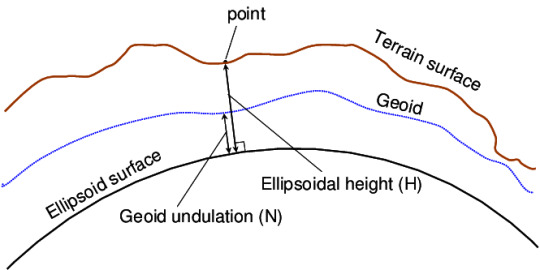
A geoid is more representative of the Earth’s surface as it takes into account the undulation and irregularities. Geoid models are very region specific, allowing for conversion from the ellipsoid to national vertical datums. Geoid height is the offset value between the geoid and ellipsoid model measured locally. The geoid offset is used to convert between ellipsoidal height and a local vertical datum.
Orthometric height is the distance between the point on the Earth’s surface and the geoid. Basically, its height below or above the Mean Sea Level (MSL) when extended onto land.
This is the height is typically used by surveyors or engineers who need accurate data.
In the US geoid height is a negative value with the exception of Alaska, where it’s a positive.
Since drone projects typically do not cover large areas applying a geoid offset can greatly improve your survey results. Fortunately, there are many online tools for determining the geoid offset for your project. The National Geodetic Survey (NGS) offers one which can be found via this link. Simply choose an image in the center of your project, record the Lat/Long and find the geoid offset for that location. Apply this offset to the altitude report in the EXIF of all images and proceed with your processing. Alternatively, your processing software may allow you to apply a geoid offset at project setup. This offset is then applied to all your image locations without you having to manually adjust all your EXIF data.
With RTK and PPK solutions that have had a geoid offset applied, you can then restrict your processing software from adjusting these values by selecting a direct georeferencing option when performing the bundle adjustment. However, since most drones capturing imagery do not have a highly accurate IMU, you will still want to allow your processing software the freedom to adjust for roll, pitch and, yaw.
Once your dataset is processed, compare to surveyed check points within your project. The results should be extremely accurate.
https://www.simactive.com/
0 notes
Link
The term benchmark, or bench mark, starts from the etched even marks that assessors made in stone structures, into which a point iron could be set to frame a bench for a leveling bar, in this way guaranteeing a leveling pole could be precisely repositioned in a similar spot later on. These marks were typically shown with an etched bolt underneath the level line.
The term is commonly applied to anything used to mark a point as an elevation reference. Habitually, bronze or aluminum plates are unchangeable or concrete, or on bars crashed profoundly into the earth to give a steady elevation point. In the event that an elevation is marked on a guide, however there is no physical mark on the ground, it is a spot height.
The height of a benchmark is determined comparative with the heights of close by benchmarks in a system stretching out from a crucial benchmark. A basic benchmark is a point with an exactly known relationship to the vertical datum of the territory, commonly mean ocean level. The position and height of every benchmark appears for enormous scope maps.
The expressions heightand elevation are frequently utilized reciprocally, yet in numerous wards they have explicit implications; height usually alludes to a nearby or relative distinction in the vertical, (for example, the height of a structure), though "elevation alludes to the distinction from a named reference surface, (for example, ocean level, or a scientific/geodetic model that approximates the ocean level known as the geoid). Elevation might be indicated as ordinary height (over a reference ellipsoid), orthometric height, or dynamic height which have marginally various definitions.
This development video instructional exercise illuminates bench mark shifting in land studying. The video is introduced by the prestigious architect S.L. Khan. A benchmark has a place with a perspective by which the estimation of something should be possible. In looking over, a "bench mark (two words) implies a post or other perpetual mark set at a distinguished elevation that is applied as the root for working out the elevation of other geological focuses.
Benchmark shifting alludes to the procedure for deciding the degree of a recently arranged point from an old known point. The procedure depends on the accompanying two conditions:-
In the event that the new point is adjoining an old point or B.M.
On the off chance that the new point is away from an old point.
In first condition, it is required to mastermind the instruments contiguous to the bench mark. This is the old bench mark, the position ought to be from rear or BS. Rear alludes to the primary site in the wake of sitting on the instrument. In the wake of picking the rear, the prescience ought to be legitimately picked on the new point.
In this way, R.L of the new benchmark
= H.I – FS
H.I means the height of instrument = old bench mark + rear (BS)
This technique is material when the focuses are adjoining one another.
This development video instructional exercise introduced by eminent designer S.L. Khan is extremely valuable for a land assessor. The video quickly clarifies benchmark shifting in land looking over.
The term benchmark, or benchmark is gotten from the etched flat marks that assessors make in stone structures, into which an edge iron is set to build up a "bench" for a leveling bar, in this manner ensuring that a leveling pole ought to be appropriately repositioned in the proportionate spot later on. These marks are commonly pointed with an etched bolt under the flat line.
The term is typically relevant to anything that is utilized to separate a point as an elevation reference. Usually, bronze or aluminum circles are organized in stone or concrete, or on poles crashed strongly into the earth to introduce a protected elevation point.
In the event that an elevation is outlined on a guide, yet there doesn't exist any physical mark on the ground, it has a place with a spot height. In looking over, a "bench mark" represents a post or other perpetual mark that is set at a perceived elevation to be applied as the reason for working out the elevation of other geographical focuses.
Bench Mark Shifting methods finding the degree of a recently arranged point concerning an old recognized point. A G.T.S. (Extraordinary Trigonometrical Survey) benchmark is a forever fixed reference overview station (or point), having known elevation as for a standard datum (mean ocean level).
These are set up all over India by Survey of India division with more noteworthy exactness. A benchmark esteem is very basic at any review territory, particularly for decrease of watched ocean level regarding mean ocean level or outline datum (CD). While completing bathymetric review of a study region, the datum referenced qualities subsequently acquired are utilized to process the last profundity forms of the overview zone (as for CD).
Along these lines, a benchmark, having realized elevation is very basic at the review region, without which, readiness of a bathymetric outline is inconceivable. In certain spots, GTS benchmarks are accessible inside a kilometer separate and can be effortlessly moved to the review territory by fly leveling utilizing a programmed Level instrument and a graduated leveling staff.
Be that as it may, in the vast majority of the cases, GTS benchmarks might be at far away good ways from the territory to be reviewed. In these cases, the most widely recognized conventional technique for moving the benchmark esteem utilizing a programmed level instrument is a troublesome assignment, expending gigantic measure of time and work. To dispense with this procedure, a strategy is proposed in this specialized report to move GTS benchmark from any far separation to the overview region.
0 notes
Photo

Braquete SAFIRA - ICERAM-S / Orthometric... 450,00 cada, entrego em Fortaleza e região metropolitana com frete grátis. #ortodontia #ortodontistas #dentistasdoceara #dentistasdefortaleza #dental #odontologia (em Fortaleza Ceará) https://www.instagram.com/p/B7qzc-pHkut/?igshid=1118pocz5n3vn
0 notes
Video
Saindo do forno a primeira remessa dos braquetes da filosofia SMS - Speedy Marden System desenvolvida pelo Prof. Marden Bastos. Ela sela a parceria entre o Instituto e a Orthometric, convertendo a escola em um campo clinico de pesquisa. Com esse acordo os alunos receberão parte dos materiais para uso nos tratamentos, diminuindo significativamente o custo dos cursos de ortodontia. Bom para todos! Obrigado Ortometric!!! (em Instituto Marden Bastos) https://www.instagram.com/p/CMepTWcJorx/?igshid=rjg8po3binzb
0 notes
Photo

We specialize in low level, high accuracy, high resolution imagery suitable for engineering design, volumetric computations and orthometric imagery to assist in exploration, flood studies and general project planning.
Our aerial survey technologies include LiDAR for rapid high density precision surface definition, thermal sensors for ground temperature analysis and hyperspectral sensors for environmental assessment and monitoring. Clients have access to the most precise data needed to make critical decisions across the life of their projects.
For more details:
Email: - [email protected]
Contact No: - +971-4-2676170.
URL: - http://www.alwarqasurvey.com/aerial-survey-and-mapping
0 notes
Text
Vertical distance from Sea level is called:
Vertical distance from Sea level is called:
A. Longitude B. Altitude C. Ephsoidal D. Orthometric
#General_Knowledge_MCQs, #Past_PPSC_Papers, #PPSC_Past_Papers_2019_MCQs https://jobexpert.pk/past-ppsc-papers/vertical-distance-from-sea-level-is-called/
0 notes
Text
Iceram braquetes ceramicos 0800-2820504
braquetes ceramicos Iceram, da Orthometric; vendidos pela Dental Supplies Ortodontia (Wayne), há 23 anos no mercado da ortodontia brasileira – ceramica policristalina, não mancha, slot hiper-polido. www.dentsup.com.br Source: Credit goes to respacted author.
The post Iceram braquetes ceramicos 0800-2820504 appeared first on International Public Health.
from International Public Health https://ift.tt/34GsPrB
0 notes
Text
Shapiro delay in PSR~J1811$-$2405. (arXiv:2002.01009v1 [astro-ph.HE])
This paper presents the first detection of Shapiro delay from the binary millisecond pulsar PSR J1811-2405. We report a 11-${\sigma}$ measurement of the orthometric amplitude, h$_3$=6.8(6)x10$^{-7}$, and a 16-${\sigma}$ measurement of the orthometric ratio, ${\varsigma}$= 0.81(5). Given the relatively high orbital inclination, i= 79(2) deg, of this binary system, we obtain constraints on the companion mass of m$_c$= 0.31$\substack{+0.08 \\ -0.06}M_\odot$. The pulsar mass is currently less well constrained, with a value of 2.0$\substack{+0.8 \\ -0.5}M_\odot$. The companion mass and the orbital period are in agreement with the prediction made by previous numerical calculations of the evolution of compact binary systems. From a study of the polarization, we find that the orbital inclination angle is ~100 deg and that PSR J1811-2405 is an orthogonal rotator. In addition, the ${\mu}$s-level timing precision together with its narrow profile make PSR J1811-2405 a good candidate for inclusion in the pulsar timing arrays being used to detect nHz Gravitational waves.
from astro-ph.HE updates on arXiv.org https://ift.tt/2GSEedh
0 notes
Last Seen Blogs

kevin-tashina999
Untitled

josephinegiselle-blog
UberEats Clone

nicky-comic
Nicky-comic

bluesdraws
Blues Draws

ricardowagnerlexington-blog
RicardoW