
Last Seen Blogs

minkystars
mimi

rainbow-of-gems
A Rainbow

aracelliworld
Aracelli World

tharannas
tharannas does art sometimes

saudiroyalclean18
تنظيف منازل
Text
IRIG-G extension to IRIG core
We recently added IRIG-G support to our IRIG core.
IRIG-G is very similar to IRIG-B but rather than transferring 1 frame per second as for IRIG-B, IRIG-G transfers 100 frames per second (so every 10ms a new frame) and has a slightly different frame format since now the concept of milliseconds is added to the frame.
For DCLS this was not really a big challenge since this just means we have now a bit rate of 10kpps rather than 100pps and we send the frame with the different Format with the millisecond information (which is only a fraction of the nanosecond resolution we have in the FPGA). On the receive side we still stick to the 1/s calculation rate for adjustments to reduce the jitter and have a more accurate drift measurement (error/s vs error/10ms). This is simply done by just using every 100th frame where the milliseconds are 0 (only 10s and 100s of milliseconds are transferred every 10ms, so for sure a frame with 0ms will be there every second).
For AM modulated IRIG-G it gets interesting since the carrier frequency for IRIG-G is 100kHz. That doesn’t sound like a lot since it is still a 10us period. Well, in our previous post (https://nettimelogic.tumblr.com/post/177445549105/irig-b12x-with-dac-and-adc-nettimelogic-just) we described how to do high accuracy IRIG AM with DACs and ADCs using some cheap ADCs and DACs with a sampling rate of max 1MSPS. This turned out to be rather tricky. If we have a sampling time of 1us (1MSPS) and a period to generate of 10us this will end up with 10 samples per period, which is not a lot. First we created a “nice” sine wave on the DAC with rather big steps in between since we only have 10 points to draw a sine wave. This looked nice, almost like a real sine wave, but on the receive side our algorithm with detecting the zero crossing and ¼ of the sine wave check for the amplitude turned out to be a bit optimistic. Between the zero crossing and the high peak we only have 1-2 samples if we are lucky and this is not good by means of oversampling, so we often ended up to sample already the falling edge of the sine wave after the first quarter resulting in the case that the receiver interpreted this as a 0 rather than a 1. So we decided to make the sine wave less a sine wave for these low oversampling rates (up to 10) but more a square wave, so going to +1 at the crossing and after half a period to -1 (or 0.3 and -0.3 for a 0). This gives us more time to still sample the high period after the zero crossing detection. Due to the DACs behavior (settling time) this looks more or less still like a sine wave but with a bit longer peak time and shorter rise/fall time.
With this little tweak we got IRIG-G AM running with the same cheap ADC/DAC we used before for IRIG-B. And with an even higher accuracy than with IRIG-B, since the 0 crossing is now much more narrow.

So the conclusion is that IRIG-G is easy to do in an FPGA when it comes to DCLS and it is still possible to do also IRIG AM with cheap ADC/DACs with a “low” (1MSPS) sampling rate . However if you get your hands on DACs and especially ADCs with a bit higher sampling rates (e.g. 2 or better 5MSPS) you are always on the save side.
0 notes
Text
High performance NTP Server
NetTimeLogic extended its portfolio of products with a long awaited high performance (S)NTP Server!
It is a SNTP Server according to RFC 4330/5905 (NTPv4) and completly handling NTP requests in the FPGA. This gives an unprecedented performance of 100k+ requests/s (~500k) with minimal resource usage and a best in class requests/watt and requests/money rate. It allows to completly offload the NTP Server functionality to the FPGA, meaning it does not need a CPU or NTP Stack at all.
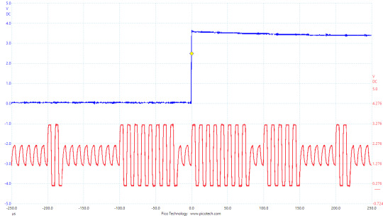
Here you can see the synchronization accuracy of a SNTP client to our server
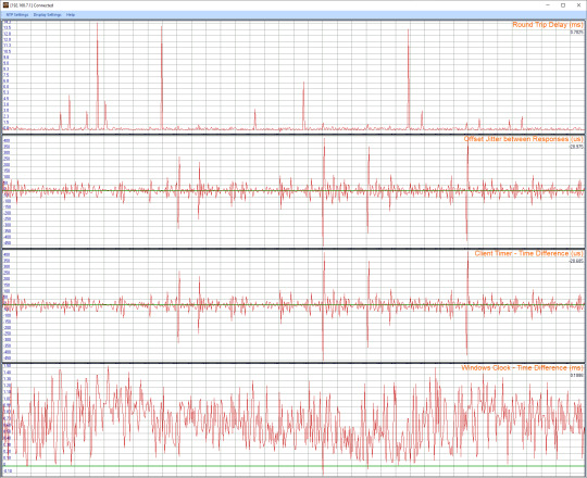
Here you can see our Server under heavy load (100k requests per second)
https://www.nettimelogic.com/ntp-server.php
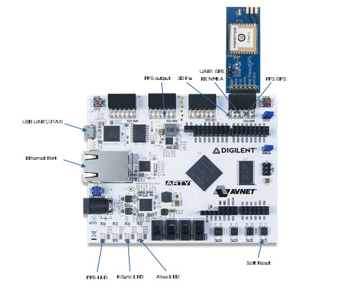
btw this is the reference design hardware we use (~250$)
0 notes
Video
NTP synchronization to our high performance NTP server, which is a fully FPGA based hardware implementation of an SNTP Server which can handle 100k+ NTP requests/s
0 notes
Text
FreeRTOS/lwIP on a NIOS II Softcore to run open62541
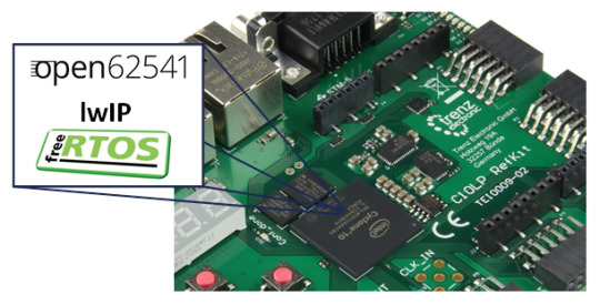
with a reference design for the Trenz Cyclone 10 LP RefKit
The Trenz Cyclone 10 LP RefKit is a very interesting Development Board on the market with an Intel (former Altera) FPGA.
In our last few blog posts, we were showing how to port open62541 to a Xilinx MicroBlaze Softcore CPU. To follow up the open62541 topic we were able to get the stack up and running also on NIOS II Softcore CPU.
Since open62541 already supports FreeRTOS with lwIP (which is also what we were using on the MicroBlaze designs), the goal was to first get FreeRTOS and lwIP running on NIOS II.
Based on a very nice NIOS II port from EngineeringSpirt (https://github.com/EngineeringSpirit/FreeLwIP-Nios-II) we have updated the sources to the latest lwIP and FreeRTOS versions. In addition some modifications were made to get it working with Quartus 18.1.
Together with the Trenz Cyclone 10 LP RefKit NIOS II reference design and the FreeRTOS/lwIP boards support package we open the possibility to get open62541 running on an Intel FPGA device with a Softcore CPU.
The forked and modified FreeLwIP-Nios II project is available here:
https://github.com/NetTimeLogic/FreeLwIP-Nios-II
The example FPGA project and the application are available here:
https://github.com/NetTimeLogic/opcua/tree/master/Src/Quartus_Project
The open62541 implementation is available here (master):
https://github.com/open62541/open62541/tree/master
Overview
The open62541 implementation is basically the same as for the MicroBlaze and therefore no further details about this implementation steps are described.
An adapted cmake file for the NIOS solution is available:
https://github.com/NetTimeLogic/opcua/blob/master/Src/SdkNios.cmake
The precompiled (AMALGAMATION) files of open62541 are part of the sources in the NIOS II project:
https://github.com/NetTimeLogic/opcua/tree/master/Src/Quartus_Project/software/FreeRTOS
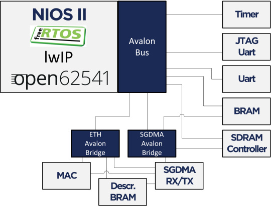
On the NIOS II the latest FreeRTOS and lwIP version are building the base for an open62541 application. On the FPGA a QSYS system is build up with all required components. The application runs from the SDRAM, and via Scatter-Gatter DMA and a TSE MAC the Ethernet handling is done. The timer is required for FreeRTOS (system tick) and the UART interfaces can be used for the printouts. The System runs on 100MHz.
The reference design is running on the Trenz Cyclone 10 LP RefKit. More details about this kit is available here:
https://shop.trenz-electronic.de/de/TEI0009-02-055-8CA-Cyclone-10-LP-RefKit-10CL055-Development-Board-32-MByte-SDRAM-16-MByte-Flash?c=473
Toolchain
To build the full project the following tools are required:
Quartus Prime 18.1 (64bit)
Nios II Embedded Design Suite 18.1
CMAKE (Python 2.7.x or 3.x)
UA Expert
Wireshark
BSP
The BSP has to be installed via the alt-freertos-lwip-install.bat script. Call this script from a command line and follow the instructions:
https://github.com/NetTimeLogic/FreeLwIP-Nios-II/blob/master/alt-freertos-lwip-install.bat
For the TSE MAC HAL driver we are not using the one of the Quartus 18.1 version. The Quartus 18.1 version requires the MSGDMA (Modular Scatter Gatter DMA) instead of the older SGDMA. Due to the existing environment which was based on the SGDMA, we have decided to not make this change right now.
Beside that, the BSP was mainly tested for the required functionality with open62541 and it is still possible that not all lwIP features are fully working (e.g. IPv6).
Most parameters are editable directly via the BSP Editor. Depending on the needs there might be still some parameters which are not in the GUI.
Design preparation
Creating the design is quite easy since the script creates a full template.
1. Go to File->New->Nios II Application and BSP from Template
2. Select FreeRTOS – LwIP Demo with the Nios.sopcinfo
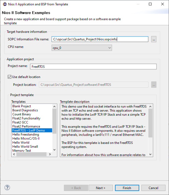
3. With the Finish Button the Demo Project will be created.
4. In the BSP the following settings must be changed:
Right Click on the BSP, NIOS II-> BSP Editor …
max_file_descriptors: 16
(Optional) stdin, stdout, stderr: uart_0
5. Close the BSP Editor and regenerate the BSP
6. The demo application can be built; however, the demo was never tested as such on the hardware.
7. Remove the files and create your own application (e.g. main.c; iicNs.c/h and open62541.c/h)
Summary
Thanks to the well prepared FreeRTOS with LwIP integration in the Nios II EDS from EngineeringSpirit it was possible to get open62541 up and running on an Intel FPGA with a soft core inside.
We have updated the existing port to the Quartus 18.1 version and also used the latest lwIP and FreeRTOS versions. The update to the latest versions, a reference design for the Trenz Cyclone 10 LP RefKit and the demo PubSub example opens new and interesting opportunities to have OPC UA running on an Intel FPGA with a SoftCore.
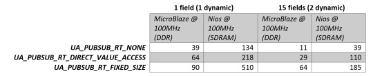
Since the open62541 application is the same as for our performance test we have quickly rerun some of them on the NIOS II CPU.
A comparison between the two softcore variants can be found in the figure below even if they are a bit hard to directly compare (both @ 100MHz, but program code is running on DDR vs SDRAM etc.). Nevertheless it shows what performance could be achieved on such a soft core CPU.

0 notes
Text
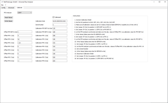
New version of the precise and low cost PPS Analyzer Shield
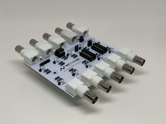
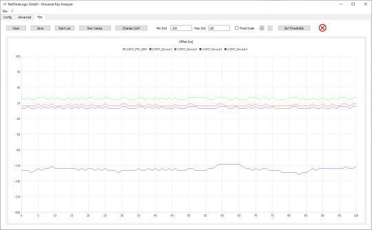
To measure the accuracy of synchronization, the comparison of Pulse Per Second (PPS) signals of the devices under tests is for sure the simplest way. With our PPS Analyzer Shield for the Digilent Arty A7 board you get a very precise (4ns resolution) and low cost solution for comparing PPS signals. One board has 8 PPS input channels, 1 reference PPS input and 1 PPS output. The Universal Pps Analyzer GUI allows longterm measurements and supports configurable thresholds with alarm outputs.
The successful first version of the PPS Analyzer Shield has been reworked with some improvements. Additionally the Universal PPS Analyzer Tool supports some new functionalities.
New Hardware features:
PPS indication LEDs on all channels
EEPROM to store buffer delay compensation values
Threshold signaling outputs on the shield
Improved mounting on Digilent Arty A7 board
Additional measurement and calibration pins
New Tool features:
Simple calibration routine in the PPS Analyzer GUI
Configurable thresholds limits for all input channels
Threshold indication
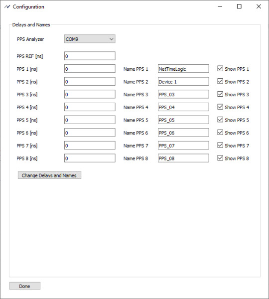
Renameable PPS signal
Persistent configurations

Additional information can be found here:
https://www.nettimelogic.com/tools-pps-analyzer.php
If you are interested in the new version of the PPS Analyzer Shield send us an e-mail: [email protected]
With the PPS Analyzer Shield and a Digilent Arty A7 Board you get a powerful and low cost equipment for your pulse per second synchronization measurements.

1 note
·
View note
Text
open62541 publishing performance on a Soft-Core CPU in an FPGA
Overview
In the first steps to get OPC UA PubSub running on MicroBlaze Soft-Core the performance was not in the focus. At the TSN/A conference in October 2019 was an interesting presentation about the processor cycles for the publisher. It was known that this is a bottleneck, especially on low performance CPUs. Therefore, an improvement with some static configuration was presented on the roadmap. At the SPS in Nurnberg we saw first figures with this performance improvement. Now it will be very interesting what does this mean on a low performance CPU like the Xilinx MicroBlaze Soft-Core in the FPGA. If this performance is sufficient, a smart combination with NetTimeLogic’s TSN products and an open62541 PubSub application in a MicroBlaze Soft-Core will fulfill many market requirements.

As a starting point, the OPC UA PubSub tutorial on a FPGA is used (OPC UA PubSub on a FPGA using open62541). To get the latest RtLevel features of the open62541 implementation the master branch is used.
The example FPGA project and the application are available here:
https://github.com/NetTimeLogic/opcua/tree/PubSub_RtLevel_example
The open62541 implementation is available here (master):
https://github.com/open62541/open62541/tree/master
Introduction
The main change compared to the previous open62541 posts is that now the master branch of open62541 is used. There were some small adjustments needed in the application code, otherwise the old tutorial on how to generate the libraries is still valid.
Also the MicroBlaze FPGA image running on the Arty A7-100T development board from DIGILENT is still unchanged.

The main focus is to compare the publish performance of frames with the different PubSub RT levels. Deterministic behavior was not investigated and also not the PubSub conformance (OPC UA part 14) since the feature is still under development.
Description of the RT Modes:
UA_PUBSUB_RT_NONE
Default "none-RT" Mode. For each DataSetField the value is read out of the information model. This is slowing down the publishing process.
UA_PUBSUB_RT_DIRECT_VALUE_ACCESS
Within this RT-mode, the value source of each field is configured as static pointer to a DataValue. The publish cycle is improved by prevent the value lookup within the information model. All fields must be configured with a static value source. The DataSetFields can still have a variable size. The published fields are not visible in the information model.
UA_PUBSUB_RT_FIXED_SIZE
All DataSetFields have a known, non-changing length. The server will pre-generate some buffers and use only memcopy operations to generate requested PubSub packages. The configuration must be frozen while it is operational. The published fields are not visible in the information model.
Design preparation
For the detailed design preparation steps please check the post OPC UA Server on a FPGA using open62541 and OPC UA PubSub on a FPGA using open62541.
Basic OPC UA Server PubSub application
In the Xilinx SDK the available OpcServer.c can be imported to the OpcServer application project.
In the basic server the thread stack size was defined with 4096. This is not enough anymore and the application will report with the hook functions a StackOverFlow. Therefore, the THREAD_STACKSIZE was increased to 16384.
In a first step the network initialization and the basic OPC UA Server configuration is done. Before the server starts, the PubSub specific setup is needed. The application is targeted to be compatible with the Pub/Sub format for the IIC TSN Testbed interoperability application.
With different defines the tested configurations can be selected.
Changes compared to the last version
For the new PubSub feature some changes compared to the previous version are needed.
On the open62541 repository are examples available how the new feature can be used. With the help of the following examples the OpcServer.c was extended.
https://github.com/open62541/open62541/blob/master/examples/pubsub/server_pubsub_publisher_rt_level.c
Beside some small cosmetic adjustments and some added defines to compile the different versions mainly three adaptations were needed. The first one is how the data set field is added (addDataSetField function), then how the data set value is updated (valueUpdateCallback) and the last one is the freeze of the writer group before publishing starts (UA_Server_freezeWriterGroupConfiguration).
addDataSetField / UA_Server_addDataSetField:
The field needs to be set as static value source and the value must be assigned. A dynamic node is not added as before because of the pointer assignment of the published value.
valueUpdateCallback:
The updates of the values is done here (Pointer to the value).
UA_Server_freezeWriterGroupConfiguration:
This must be done before the publishing starts (only for the RT modes). It means that no dynamic changes of the write group are possible anymore. Before any change can be done, publishing must be stopped and the command UA_Server_unfreezeWriterGroupConfiguration called.
Measurements
As already mentioned in the beginning, the tests are only focusing on how many frames can be published. For all tests the same pub sub message was used and the measurement was done over 180 seconds. The MicroBlaze Soft-Core is running on 100MHz. No other connections to the server (e.g. disconnect UA Expert) are established.
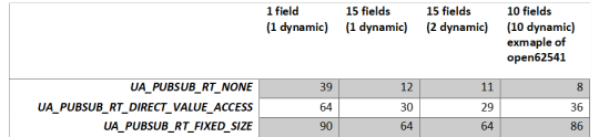
The measurement was done with three different payload configurations for the three different modes. The header was always the same (Timestamp deactivated).
1. 1 published variable, with 1 dynamic value (payload: 24 bytes)

2. 15 published variables, with 1 dynamic value (payload: 182 bytes)
3. 15 published variables, with 2 dynamic values (payload: 182 bytes)
As a fourth frame format the example RT level PubSub application from open62541 was also tested. This has 10 published variables and all are dynamic (payload 80 bytes)

Measurement overview:

Observed problems with the RtLevel UA_PUBSUB_RT_FIXED_SIZE:
Header information update seems no to work as for the other modes (e.g Seq.-Nr).
With UA_UADPNETWORKMESSAGECONTENTMASK_TIMESTAMP enabled the dynamic value does not update anymore. Therefore, all tests were done without this flag. The reason was not investigated.
Summary
The RT level PubSub update of open62541 brings a substantial performance improvement already on a very low performant CPU. With the enhancement, also some limitations were added. Dynamic changes of the published Datasets are not possible while it is operational. This is most probably negligible for many applications. Another constraint of the RT level is that the values are not visible in the information model anymore. Updating the information model would decrease again the performance.
Especially the RT_FIXED_SIZE concept does show the benefit when many fields are published. It seems definitely as an option to use open62541 in combination with a Soft-Core in the FPGA. Of course, high-performance applications can’t be achieved, but for such cases usually a high perfmance CPU is anyhow already in place for the application part.
However, there are still some open points when it comes to dynamic fields of the header like timestamps or sequence number. There seems to be some remaining work (Updates in the header in the UA_PUBSUB_RT_FIXED_SIZE mode).
Some general updates in the header seems not to work as expected:
GroupHeader
GroupVersion was not assigned
SequenceNumber was not assigned
ExtendedNetworkMessageHeader
Timestamp was empty
For our testing we have done the same quick fix as described in the previous post.
As a next step the deterministic behavior will be the focus. Preferable already in combination with our TSN End Node.
0 notes
Text
OPC UA PubSub on a FPGA using open62541
Overview
In a first step a simple OPC UA server was set up on a FPGA (see our previous blog post: OPC UA Server on a FPGA using open62541). As a starting point it would be good to begin with this example since the PubSub description builds up on the basic OPC UA server.
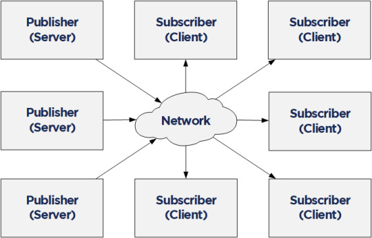
Compared to the Client/Server mechanism, the Publish/Subscribe model is even more interesting in the context of Time Sensitive Networking (TSN). PubSub is defined in Part 14 of the OPC Unified Architecture specification and it allows one-to-many or many-to-many connections. In combination with a TSN sub-layer it can fulfill the real-time requirements for the industry.
Together with NetTimeLogic’s TSN products or the TSN IIC® Plugfest Application (Talker/Listener) an open62541 PubSub application in a MicroBlaze Softcore can be easily combined. For the future we are targeting to realize the TSN Testbed Interoperability Application with the open62541 OPC UA stack and using NetTimeLogic’s TSN End Node IP core as realtime sub-layer.
The example FPGA project and the application are available here:
https://github.com/NetTimeLogic/opcua/tree/PubSub_example
The open62541 implementation is available here (v1.0rc5):
https://github.com/open62541/open62541/tree/v1.0-rc5
Introduction
Compared to the Client/Server example no changes in the MicroBlaze FPGA design are needed. However, some adjustments in the CMake and BSP for lwip are required.
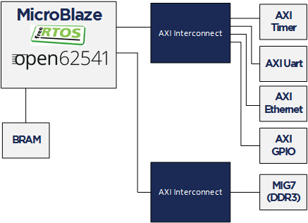
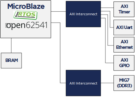
The following implementation is based on the open62541 documentation which describes how to build the library and how to work with Publish/Subscribe. The application creates an OPC UA server thread which is publishing a Dataset. It runs with FreeRTOS and lwip. The FPGA use a MicroBlaze softcore with DDR3, Axi Ethernet Lite, Axi Uart Lite AXI GPIO and AXI Timer. As hardware the same Arty A7-100T development board from DIGILENT as before is used.
Required tools
To build the full project, the following tools are required:
To build the full project following tools are required:
Xilinx Vivado 2019.1
Xilinx SDK 2019.1
CMAKE (Python 2.7.x or 3.x)
UA Expert
Wireshark
BSP adjustments for LWIP
For the simple OPC UA server some adjustments were needed in the lwip BSP of Xilinx SDK.
See Line 10-19: https://github.com/open62541/open62541/blob/master/arch/common/ua_lwip.h
The Pub/Sub functionality need some more adjustments of the BSP. It should be enough to enable the LWIP_IGMP. Nevertheless, it was not possible to generate successfully the BSP again with this option enabled. As a workaround the additional needed defines are added to the already created (in the previous post) open62541 section in the lwip211.tcl (bold) file. This allows to use the standard compilation flow afterwards .
1. Go to:
C:\Xilinx\SDK\2019.1\data\embeddedsw\ThirdParty\sw_services\lwip211_v1_0\data
2. Open the lwip211.tcl
3. Search the proc generate_lwip_opts {libhandle} and go to the end of this procedure
4. Before the line puts $lwipopts_fd “\#endif” add the following code:
#OPEN62541 implementation
set open62541_impl [expr [common::get_property CONFIG.open62541_impl $libhandle] == true]
if {$open62541_impl} {
puts $lwipopts_fd “\#define LWIP_COMPAT_SOCKETS 0”
puts $lwipopts_fd “\#define LWIP_SOCKET 1”
puts $lwipopts_fd “\#define LWIP_DNS 1”
puts $lwipopts_fd “\#define SO_REUSE 1”
puts $lwipopts_fd “\#define LWIP_TIMEVAL_PRIVATE 0”
puts $lwipopts_fd “\#define LWIP_IGMP 1”
puts $lwipopts_fd “\#define LWIP_MULTICAST_TX_OPTIONS 1”
puts $lwipopts_fd “”
}
5. Save the file
After this change and a restart of Xilinx SDK the new option will be visible in the BSP settings GUI of the lwip stack.
Design preparation
For the detailed design preparation steps please check the previous post OPC UA Server on a FPGA using open62541.
Custom information models
In the basic OPC UA server example the default value “reduced” is used as UA_NAMESPACE_ZERO option. For the UA_ENABLE_PUBSUB option it will compile an additional nodeset and datatype file into the name space zero generated file. Depending on what information will be published this might be not enough.
To be on the safe side UA_NAMESPACE_ZERO = “FULL” would be the easiest solution. Since the MicroBlaze CPU is not a very powerful, it is not recommended to use the full namespace. This example would take up to 30 minutes, until the server is up and running! It is highly recommended to use an optimized/customized nodeset for such an application.
https://opcua.rocks/custom-information-models/
XML Nodeset Compiler
Most probably in a final application all the variables/objects etc. are not defined manually in the code. There are different tools (commercial but also open source) available to create this information in a GUI. Out from these tools an XML with the OPC UA Nodeset schema can be exported.
Open62541 provides a compiler which creates C code from the XML Nodeset. This code creates then all the object instances as defined.
The complete documentation can be found here:
https://open62541.org/doc/1.0/nodeset_compiler.html
The compiler result for iicNs.c/h are available in git.
Nodeset in this example
Since this example is targeting for the IIC TSN Testbed application, the Nodeset from there is used. It has the following structure with different types of variables:
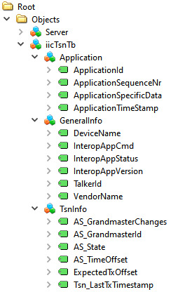
For this Information Model the minimal Nodeset with PubSub is not sufficient, therefore a customized one was created. This can be done as described above, or even simpler, just by using the already precompiled open62541.c/h files
CMAKE
For this example, the open62541 tag v1.0rc5 was used:
https://github.com/open62541/open62541/tree/v1.0-rc5
The easiest way is to work with the CMake GUI. Later it can be used in Xilinx SDK.
If the CMake library build is already available only two adjustments are needed:
UA_ENABLE_PUBSUB = ON
UA_ENABLE_PUBSUB_INFORMATIONMODEL = ON
If a new build is created, CMake for open62541 is used with the following adjustment:
UA_ENABLE_AMALGAMATION = ON
UA_ENABLE_HARDENING = OFF
UA_ENABLE_PUBSUB = ON
UA_ENABLE_PUBSUB_INFORMATIONMODEL = ON
UA_ARCH_EXTRA_INCLUDES = <path to microblaze/include>
UA_ARCH_REMOVE_FLAGS = -Wpedantic -Wno-static-in-inline -Wredundant-decls
CMAKE_C_FLAGS = -Wno-error=format= -mlittle-endian -DconfigUSE_PORT_OPTIMISED_TASK_SELECTION=0 -DconfigAPPLICATION_ALLOCATED_HEAP=3 -DUA_ARCHITECTURE_FREERTOSLWIP
UA_LOGLEVEL = 100 (optional for debugging)
1. Start the CMake GUI
2. Select the correct source code path where the open62541 GIT repository is located and the path where the binaries were built last time:
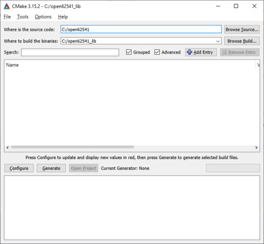
3. Click Configure
4. Change the two parameters:
UA_ENABLE_PUBSUB = ON
UA_ENABLE_PUBSUB_INFORMATIONMODEL = ON
5. Click again on Configure and after that on Generate
6. Generate again the open62541.c/h file in Xilinx SDK.
Make Target->all
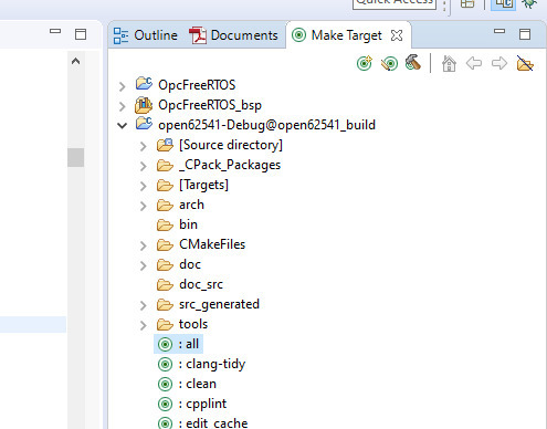
7. The amalgamation files open62541.c/h should have now the PubSub feature included
A pre-generated version of the open62541.c/h files is available on git.
Creating the OPC UA server application
The complete SDK workspace is available on git.
C/C++ Build Settings
For the build there are no new adjustments required. Please take the same build settings as in the previous post for the simple OPC UA Server.
Linker script
The linker script setting for the memory must be increased, In the example we use now:
Heap Size: 20MB
Stack Size: 20MB
OPC UA Server PubSub application
In the Xilinx SDK, the available OpcServer.c can be imported to the OpcServer application project.
In the basic server the thread stack size was defined with 4096. This is not enough anymore and the application will report with the hook functions a StackOverFlow. Therefore, the THREAD_STACKSIZE was increased to 16384.
In a first step the network initialization and the basic OPC UA Server configuration is done. Before the server starts, the PubSub specific setup is needed. The application is targeting to be compatible with the Pub/Sub format for the IIC TSN Testbed interoperability application
Define the PubSub connection
In the PubSub connection mainly the transport profile and the multicast network are defined. For this case we used following settings:
transportProfile: http://opcfoundation.org/UA-Profile/Transport/pubsub-udp-uadp
Network Address URL: opc.udp://224.0.0.22:4840
Add a Publishing dataset
This is the collection of the published fields. All PubSub items are linked to this one.
As PublishedDataSetType the following configuration is used:
publishedDataSetType: UA_PUBSUB_DATASET_PUBLISHEDITEMS
Add fields (variables) to the dataset
Here the variables are added by their NodeIds to the Published data set. Depending on the configuration the order of adding the variables has an impact how the published data will look like.
Additionally, a value is set. It is important that the variables have a value (not NULL). If a variable is empty there is just no content for the DataMessage to publish in the PubSub frame.
Add the writer group
The writer group is the important part when it comes to how the message looks like. The whole configuration for the NetworkMessage Header (Extended) is done here (OPC UA Part 14 Chapter 7.2.2.2).
Open62541 allows the specific configuration with the networkMessageContentMask configuration.
For the IIC TSN Testbed interoperability application following settings will be used:
writerGroupMessage->networkMessageContentMask = (UA_UADPNETWORKMESSAGECONTENTMASK_PUBLISHERID | UA_UADPNETWORKMESSAGECONTENTMASK_GROUPHEADER | UA_UADPNETWORKMESSAGECONTENTMASK_WRITERGROUPID | UA_UADPNETWORKMESSAGECONTENTMASK_GROUPVERSION | UA_UADPNETWORKMESSAGECONTENTMASK_NETWORKMESSAGENUMBER | UA_UADPNETWORKMESSAGECONTENTMASK_SEQUENCENUMBER | UA_UADPNETWORKMESSAGECONTENTMASK_PAYLOADHEADER | UA_UADPNETWORKMESSAGECONTENTMASK_TIMESTAMP);
Beside the NetworkMessage Header also settings like the publishing interval or the encoding MimeType are done here.
Add the dataset writer
This part is the second important part and defines how the DataSetMessage Header looks like (OPC UA Part 14 Chapter 7.2.2.3.4).
With the dataSetMessageContentMask and the dataSetFieldContentMask this can be configured.
For the IIC TSN Testbed interoperability application all this additional information is disabled:
dataSetWriterMessage->dataSetMessageContentMask = UA_UADPDATASETMESSAGECONTENTMASK_NONE;
dataSetWriterConfig.dataSetFieldContentMask = UA_DATASETFIELDCONTENTMASK_NONE;
Start the Server
After all the setup for the variables and the PubSub data set has been done the server is ready to start.
Starting the server takes quite some time with this example. After about two minutes the OPC UA Server starts publishing.
Listen to the OPC UA publisher
If there is no Subscriber available there are other options to understand a bit how the variables are published. Either the UaExpert can give some information or via Wireshark the real PubSub Frame can be analyzed.
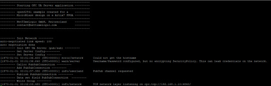
Before a connection to the OPC UA server is possible the application needs to be compiled and started on the FPGA. After a successful start you should see the following printout on in the Terminal:
UA Expert
UA Expert is also a helpful tool to check some stuff about PubSub. With the option UA_ENABLE_PUBSUB_INFORMATIONMODEL the published dataset information is available.
All the configured nodes from the previous steps are now visible (UADP Connection, PublishedDataSets, DataSetWriter etc.) as a structure directly from the server.
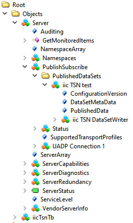
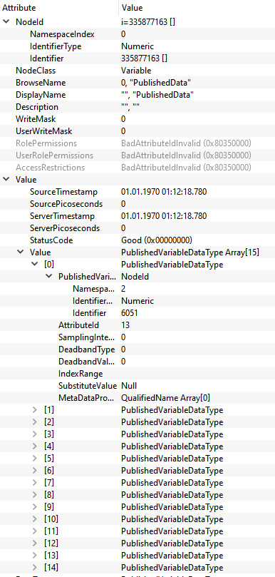
In the Attribute of the object PublishedData all the published variables are visible.
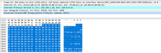
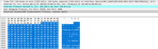
Wireshark
To check if the content of the published frame manually, Wireshark is the simplest way. This sample application uses a publishing interval of 5000 ms, so every 5s a published frame is received in Wireshark.
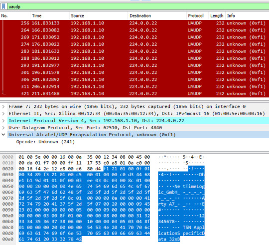
Looking into the encoding of the frame above the following information is published:

Summary
The used version of open62541 (v1.0rc5) allows working with Pub/Sub and allows to do most of the configurations for the header information. However, there were some adaptations required to use it for the IIC TSN Testbed interoperability application.
In our test we saw some problems with some header information.
GroupHeader:
GroupVersion was assigned
SequenceNumber was not assigned
Extended NetworkMessageHeader:
Timestamp was empty
As a workaround we have made some adaptations in the file src/pubsub/ua_pubsub.c by adding some assignments after the following code line:
nm.groupHeader.writerGroupId = wg->config.writerGroupId;
add:
nm.groupHeader.groupVersion = wgm->groupVersion;
nm.groupHeader.sequenceNumber = sequenceNumber;
nm.timestamp = UA_DateTime_now();
With these adjustments it was possible to create the frame as shown in the Wireshark capture.
In a next step we will try to be fully compatible with the IIC TSN Testbed interoperability application and combine it with our TSN core for real time publishing.
0 notes
Text
OPC UA server on a FPGA using open62541
Overview
Open Platform Communications Unified Architecture (OPC-UA - IEC62541) is a standardized platform-independent architecture which provides a service-based data exchange. In combination with TSN it allows new possibilities when it comes to high interoperability and deterministic communication.
Based on the open62541 implementation the following steps show how everything has to be setup to get it up and running on a FPGA (Artix7 with MicroBlaze). In combination with NetTimeLogic’s complete FPGA based TSN solution you get the full solution for industrial communication 4.0.
The example FPGA project and the application are available here:
https://github.com/NetTimeLogic/opcua
The open62541 implementation is available here:
https://github.com/open62541/open62541
Introduction
It is not straight forward to get the open62541 OPC UA stack up and running on an embedded system even if FreeRTOS and lwip is supported. The following implementation description is based on the open62541 documentation which describes how to build the library and how to implement a basic OPC UA server. The application creates an OPC UA server thread which is running under FreeRTOS with lwip.
The FPGA use a MicroBlaze softcore with DDR3, Axi Ethernet Lite, Axi Uart Lite AXI GPIO and AXI Timer. As hardware an Arty A7-100T development board from DIGILENT is used.
Required tools
To build the full project, the following tools are required:
Xilinx Vivado 2019.1
Xilinx SDK 2019.1
CMAKE (Python 2.7.x or 3.x)
UA Expert
BSP adjustments for LWIP
Open62541 supports “freertosLWIP” as an architecture. In that case it uses the libraries of the target device which are the ones of the BSP in Xilinx SDK.
To be able to compile the open62541 library some adjustments for the lwipopts.h file are needed:
Line 10-19 https://github.com/open62541/open62541/blob/master/arch/common/ua_lwip.h
Since this file is managed by the BSP in Xilinx SDK, manual modifications are overwritten when the BSP is generated. With the following workaround, it is possible to add the additional defines over the BSP setting GUI.
1. Go to: C:\Xilinx\SDK\2019.1\data\embeddedsw\ThirdParty\sw_services\lwip211_v1_0\data
2. Open the lwip211.tcl
3. Search the proc generate_lwip_opts {libhandle} and go to the end of this procedure
4. Add before the line puts $lwipopts_fd "\#endif" the following code:
#OPEN62541 implementation
set open62541_impl [expr [common::get_property CONFIG.open62541_impl $libhandle] == true]
if {$open62541_impl} {
puts $lwipopts_fd "\#define LWIP_COMPAT_SOCKETS 0"
puts $lwipopts_fd "\#define LWIP_SOCKET 1"
puts $lwipopts_fd "\#define LWIP_DNS 1"
puts $lwipopts_fd "\#define SO_REUSE 1"
puts $lwipopts_fd "\#define LWIP_TIMEVAL_PRIVATE 0"
puts $lwipopts_fd ""
}
5. Save the file
6. Open the file lwip211.mld
7.Add the new Parameter e.g. at line 47:
PARAM name = open62541_impl, desc = "Used as an open62541 implementation?", type = bool, default = false;}
8.Save the file
9. Restart Xilinx SDK
After this change and a restart of Xilinx SDK the new option will be visible in the BSP settings GUI of the lwip.
Design preparation
Before everything is ready to build the open62541 library, the implemented FPGA design from Xilinx Vivado and a software application project in Xilinx SDK is needed. In this example project a MicroBlaze design with DDR3 is used (unfortunately the application does not fit into the available block RAM).
Vivado
The Vivado project can be created with the available tcl script. By running the implementation of the Vivado project the bitstream can be created. With File->Export->Export Hardware the hardware definition can be created.
File->Launch SDK starts the SDK.
Xilin SDK
In Xilinx SDK a new empty Application Project with the OS Platform “freertos10_xilinx” can be created.
File->New->Application Project.
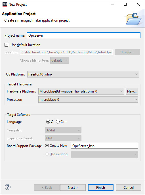
After the project is created some adjustments in the OpcServer_bsp are needed
Select lwip211 as supported libraries
Go to the lwip211 and adjust following parameter:
api_mode = socket_API
open62541_impl = true
Go to the freertos20_xilinx and adjust the following parameters:
Check_for_stack_overflow = 1
total_heap_size = 2097152
Re-generate BSP sources
The environment is now ready to start with CMake.
CMake
The easiest way is to work with the CMake GUI. Later it can be used in Xilinx SDK.
CMake for open62541 is used with following adjustment:
UA_ENABLE_AMALGAMATION = ON
UA_ENABLE_HARDENING = OFF
UA_ARCH_EXTRA_INCLUDES = <path to microblaze/include>
UA_ARCH_REMOVE_FLAGS = -Wpedantic -Wno-static-in-inline -Wredundant-decls
CMAKE_C_FLAGS = -Wno-error=format= -mlittle-endian -DconfigUSE_PORT_OPTIMISED_TASK_SELECTION=0 -DconfigAPPLICATION_ALLOCATED_HEAP=3 -DUA_ARCHITECTURE_FREERTOSLWIP
UA_LOGLEVEL = 100 (optional for debugging)
1. Start the CMake GUI
2. Select the correct source code path where the open62541 GIT repository is located and define the path where you want to build the binaries:

3. Click Configure:
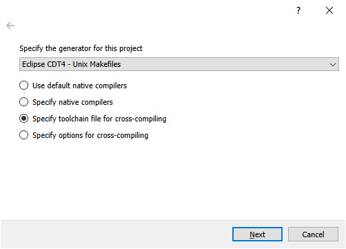
4. Select the CMake file which defines the compilation toolchain and other settings:

5. Click again on Configure and after that on Generate
6. The Unix Makefiles are now ready and can be added Xilinx SDK workspace:
File->Open Projects from File system
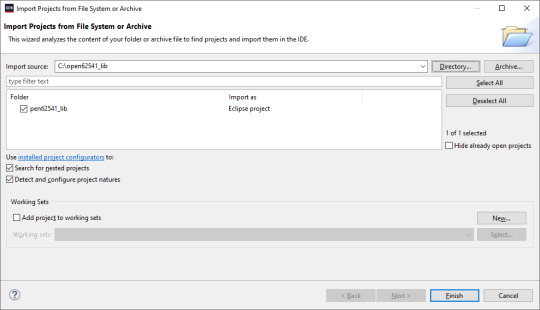
7. Now it should be possible to generate the open62541.c/h file in Xilinx SDK.
Make Target->all

8. The workspace should have now following structure:

Creating the OPC UA server application
C/C++ Build settings
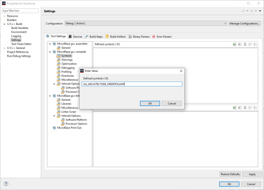
For a compilation without errors some adjustments in the application project Build settings are required.
1. Add the symbol for UA_ARCHITECTURE_FREERTOSLWIP
2. Add the open62541 build directory as include path
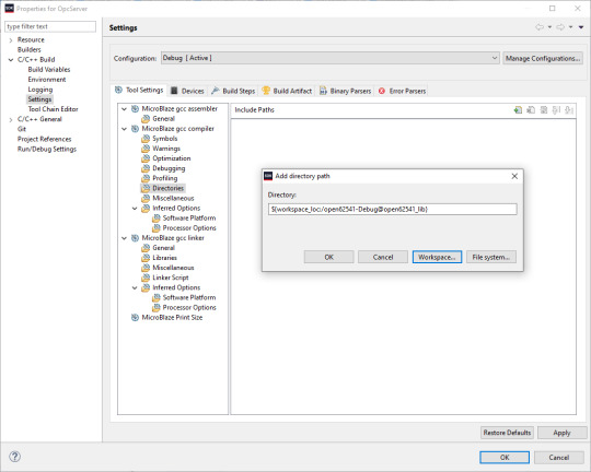
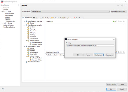
3. Add the open62541 build directory as library search path
4. Link the folder to the source location of open62541.c/h

5. Add an exclusion pattern that only the open62541.c/h are used:

Linker script
The linker script for our OPC UA server application needs some small adjustments.
With Xilinx->Generate linker script a new lscript.ld with following settings can be created:
Heap Size: (min) 1MB
Stack Size: (min) 1MB

Now the application project should be ready for a successful compilation.
OPC UA Server app
The complate Workspace is here available:
https://github.com/NetTimeLogic/opcua/tree/master/Src/Sdk_workspace
In Xilinx SDK the source file OpcServer.c can be imported to the OpcServer application project.
The thread stack size is defined with 4096 it might be possible that the application is not running properly with other values. However, the hook functions for MallocFailed or StackOverflow might be helpful.
In a first step the network initialization is done. This includes auto negotiation, ip configuration, interface binding and starting the lwip receive thread. After that the opcua thread gets started.
Important for a working server is the configuration and especially the buffer size of the network layer. With the following settings, the server was running without any problems:
config->networkLayers->localConnectionConfig.recvBufferSize = 32768; config->networkLayers->localConnectionConfig.sendBufferSize = 32768; config->networkLayers->localConnectionConfig.maxMessageSize = 32768;
Before the server is started an object and a variable are added to the server. Additionally, a callback for the variable is configured, which allows to control the LEDs on the ArtyA7 board by an OPC client. After that the server gets started and runs until the running variable is set to false (never in this case).
Connecting to the OPC UA Server
After a successful implementation of the MicroBlaze FPGA design, building the open62541 library and compiling the OPC UA server application everything is ready.
The Arty A7 board should be connected to the PC over USB and the RJ45 is connected to a network interface adapter.
1. Open a serial terminal for the debug print out (baud rate: 115200)
2. Loading the bitstream (from Vivado or SDK)
3. Run the Application (from SDK)
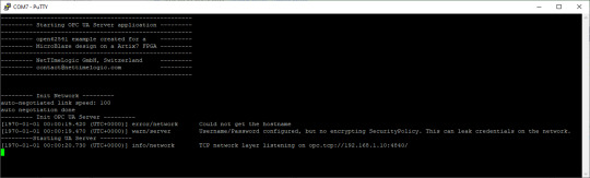
4. If the application has successfully started, in the serial terminal following text is printed out:
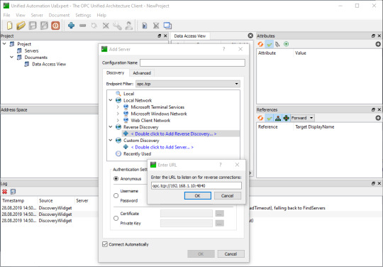
5. Start UaExpert
6. Add the server via “Custom Discovery” with the configured open62541 hostname
7. Expand the added server to add the connection. In the serial terminal you get already some information that a new connection over TCP was detected
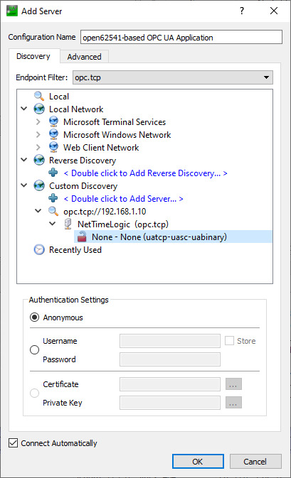
8. After a successful connection in UaExpert the defined object a variable are visible.
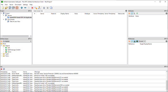
9. The variable LED can now be added to the Data Access View via drag & drop
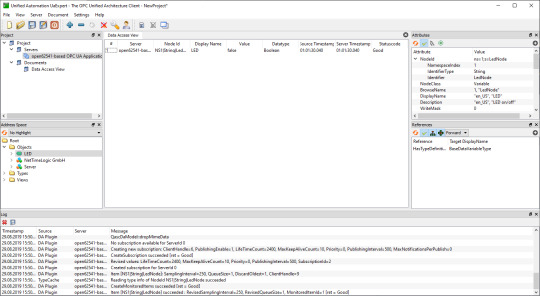
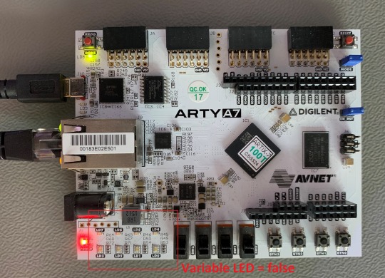
10. By changing the boolean value of the variable, the LEDs on the ArtyA7 can be switched on /off.

Summary
To get an open62541 server running on a MicroBlaze softcore following adjustments are needed:
Add the defines in the lwip BSP for lwipopts.h:
#define LWIP_COMPAT_SOCKETS 0
#define LWIP_SOCKET 1
#define LWIP_DNS 1
#define SO_REUSE 1
#define LWIP_TIMEVAL_PRIVATE 0
Adjust the BSP settings for lwip:
api_mode = socket_API
open62541_impl = true
Adjust the BSP settings for FreeRTOS:
Check_for_stack_overflow = 1
total_heap_size = 2097152
Adjust CMake options for open62541:
UA_ENABLE_AMALGAMATION = ON
UA_ENABLE_HARDENING = OFF
UA_ARCH_EXTRA_INCLUDES = <path to microblaze/include>
UA_ARCH_REMOVE_FLAGS = -Wpedantic -Wno-static-in-inline
-Wredundant-decls
CMAKE_C_FLAGS = -Wno-error=format= -mlittle-endian
-DconfigUSE_PORT_OPTIMISED_TASK_SELECTION=0
-DconfigAPPLICATION_ALLOCATED_HEAP=3
-DUA_ARCHITECTURE_FREERTOSLWIP
UA_LOGLEVEL = 100 (optional for debugging)
Generate a linker script with at least: 1MB heap and 1MB stack
Adjust the C/C++ build settings / include sources/libraries
Define the thread stack size to 4096
Adjust the buffer size of the server config:
config->networkLayers->localConnectionConfig.recvBufferSize = 32768;
config->networkLayers->localConnectionConfig.sendBufferSize = 32768;
config->networkLayers->localConnectionConfig.maxMessageSize = 32768;
1 note
·
View note
Text
IRIG-B12x with DAC and ADC
NetTimeLogic just released the AC amplitude modulated versions of its IRIG Master and IRIG Slave IP cores and we will give you some insight to our solution. In this post we want to explain how high accuracy (<2 us) IRIG-B12x (sine wave encoded, amplitude modulated IRIG-B) can be implemented using cheap DACs and ADCs.
As with all NetTimeLogic IP cores this is also an FPGA only solution (no software required), however some aditional Analog/Digital converter chips are required. The goal of this solution is to get highest accuracy synchronization, with minimal costs.
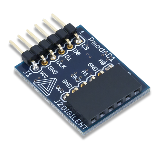
The solution is using external DACs (Digital to Anlog Converter, Digilent PmodDA2) and ADCs (Analog to Digital Converter, Digilent PmodAD1) for the handling of the analog sine wave of IRIG-B12X.
This is how our setup looks like: We use two Digilent ArtyA7-100 for our development, one is acting as an IRIG Master (with the DAC), the other is acting as an IRIG Slave (with the ADC) and we are comparing the PPS (Pulse Per Second) from the two counter clocks which are synchronized via IRIG-B127

The PmodDA2 module is a Digital to Analog Converter board from Digilent in a PMOD format featuring a Texas Instruments DAC121S101 DAC which is a 12bit DAC with a maximum sample rate of 1 mega sample per second and a SPI like interface.

The PmodAD1 module is a Analog to Digital Converter board from Digilent in a PMOD format featuring a Analog Devices AD7476A ADC which is a 12bit ADC with a maximum sample rate of 1 mega sample per second and a SPI like interface.
The sine wave encoding and decoding as well as the ADC and DAC controllers are completly independent modules in the FPGA.
On the DAC side, the encoder takes a DCLS (DC level shift) IRIG-B signal comming from the NetTimeLogic IRIG Master and converts it into an aligned (with the local counter clock) sine wave signal as samples of N bits (configurable depending on the DAC) with a modulated amplitude for 0/1 encoding for the DAC. The number of samples per sine wave period and bits per sample are configurable to allow all kind of DACs. The amplitude is encoded in a way that it uses the full DAC range for a logic one and 1/3 of the amplitude for a logic zero. Then a simple SPI controller is triggered for each sample which it then feeds to the DAC over a SPI like interface at 12.5MHz. With this setup a sample rate of 500kHz (based on the counter clock) is used.
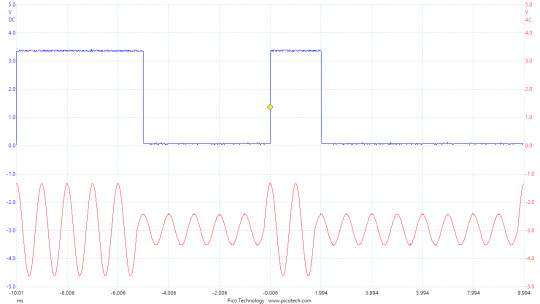
The picture below shows how the IRIG-B00x signal is aligned with the generated IRIG-B12x signal. Amplitude changes happen at the level change of the DC signal. The analog signal is sligtly shifted by the DAC delay for the convertion and the SPI access. This delay can be configured in the NetTimeLogic IRIG Master as output delay and will be compensated accordingly, so the sine wave is perfectly aligned with the counter clock.

On the ADC side, a simple SPI controller reads the voltage value from the ADC via an SPI like interface every 2 us (based on the local clock) which equals to a sample rate of 500kHz. These samples are then feed to the decoder. The decoder does an automatic signal, offset, range and zero crossing detection and converts the sine wave samples into a DCLS IRIG-B signal which is then feed as input to the NetTimeLogic IRIG Slave.
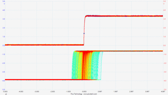
The picture below shows how the IRIG-B12x signal is aligned with the decoded IRIG-B00x signal. DCLS changes happen 1/4 of a sine wave period after the zero crossing of the sine wave (at the first positive peak after the zero crossing). This because this is the first deterministic point where the amplitude can be checked to determine if a zero or one was modulated. This constant offset is no issue, since in the NetTimeLogic IRIG Slave this value can be configured as input delay and will be compensated for accordingly. Additionaly the ADC delay for the convertion and reading over SPI shall be added to the input delay to achive high accuracy synchronization without offset.
The synchronization accuracy can be checked by comparing the PPS of the two modules which are feed to a pin. A rising edge marks the beginning of a new second on the counter clock.
With the setup described above a synchronization accuracy of less than 1.5us can be achieved.
For more information check www.nettimlogic.com
Update: After some fine tuning of the servo parameters the accuracy has improved to less than +/- 800ns. Since the detection of the zero crossing higly depends on the accuracy of the ADC, noise and the sampling rate, differnet PI servo paramters were choosen to make it slower and filtering out this sources of inaccuracy.

0 notes
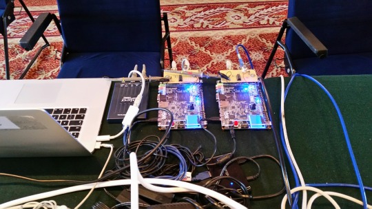
Photo
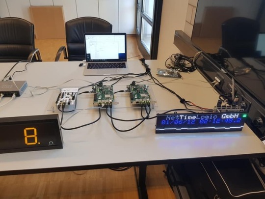
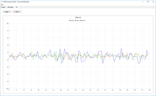

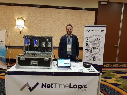
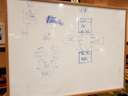
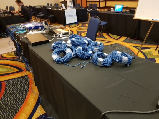
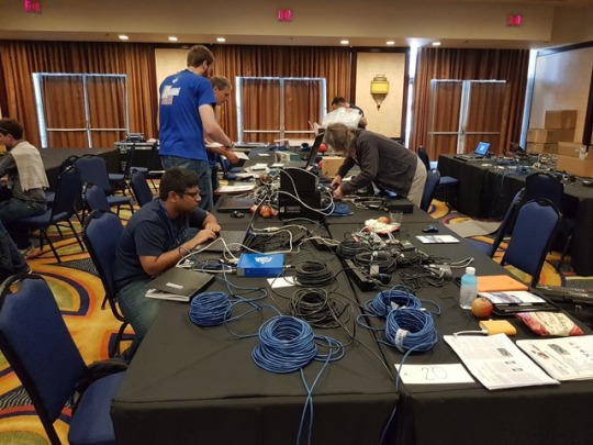
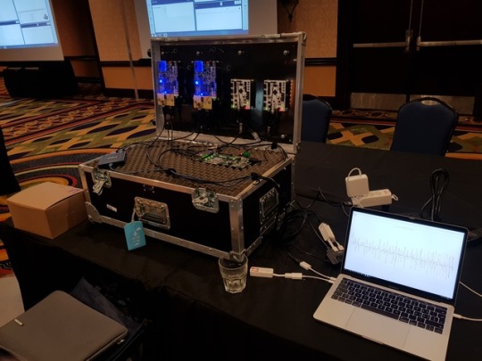
We finalized our demo setup for TSNA, showing TSN with synchronization, redundancy (also HSR&PRP), priority queues, preemption, scheduling, cylclic forwarding, credit shaping and more.
We created a TSN cycle analyzer to check where frames are received within a cycle as well as a synchronization accuracy tool which shows the measured offset to the reference from all slaves.
For more information check www.nettimelogic.com
Update: We updated the setup so each frame going to the TSN cycle analyzer is tagged with a VSS tag which contains a nanosecond accuracy timestamp of when the frame was sent. This eliminates the jitter introduced by the host PC which took timestamps in the driver.

0 notes
Photo

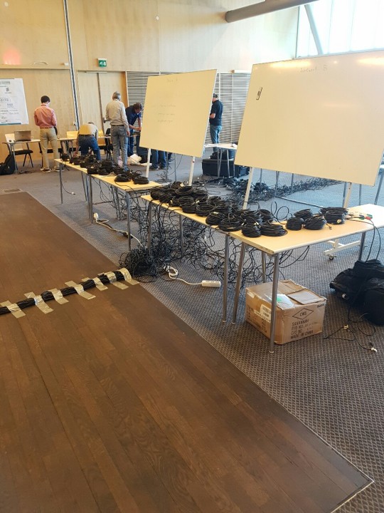
We are happy to announce that the swiss PTP Plugfest will take place at the 28th of November at the Zurich University of Applied Sciences (ZHAW) in Winterthur, Switzerland. Registration is open to everyone with a IEEE1588/PTP device. Register now: http://ptpplugfest.com/register.php See you there!
0 notes
Photo
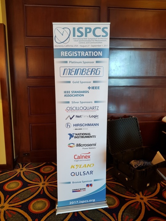


ISPCS 2017 in Monterey, USA visit ispcs.org for more pictures and infos about the event
0 notes


Text
NetTimeLogic on Tumblr
Just joined tumblr, another platform for news about NetTimeLogic’s development
0 notes