kynixsemiconductor08
Kynix Semiconductor
A professional sales platform for electronic components. Welcome to visit our website for professional purchasing guidance.
32 posts
Don't wanna be here? Send us removal request.
Last Seen Blogs

haught0pocket
Don't Mind Me

thatskindasilly
i can be trusted with a gun

myeonzen
myeon

mother-milk
mother milk

auteezm0
Auteezm0
Text
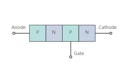
What is a Thyrsitor?
A new article gives you a detailed introduction about thyristors. Click for further reading if you’re into electroncis. :)
7 notes
·
View notes
Text
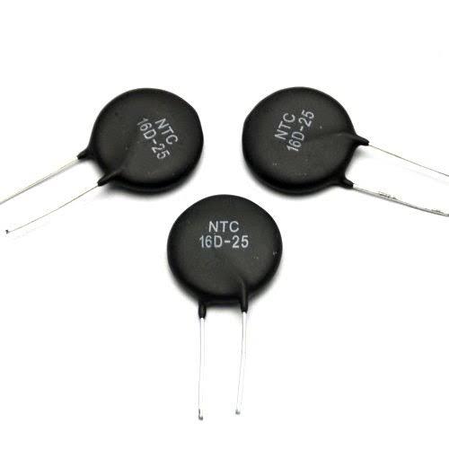
How Does NTC Thermistor Work?
This is an article about basic knowledge of NTC thermistors. Enjoy reading it!
1 note
·
View note
Text
How to Measure a Thermistor?
How to Measure a Thermistor?

I Overview of Thermistors
Like Resistance Temperature Detectors(RTDs), thermistors are temperature-sensitive semiconductors whose impedance changes with temperature. Thermistors are manufactured from metal oxide semiconductor materials packed with glass or epoxy beads. Moreover, the typical nominal impedance value of thermistor is much higher than that of the RTD, which is from 2000Ω to…
View On WordPress
1 note
·
View note
Text
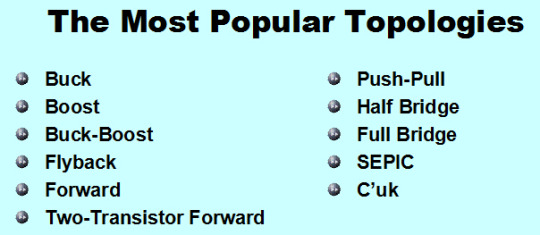
Top 12 Popular Switching Power Supply Topologies
A good article introducing some popular switching power supply topologies.
Have fun reading it :)
0 notes
Text
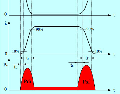
SWMP Power Loss and Efficiency
All you want to know about the power loss and efficiency of switch mode power supply.
0 notes
Text
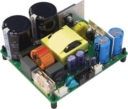
Topologies and Formulas of Switched Mode Power Supply
A comprehensive introduction of the topologies and formulas of switched mode power supply. Enjoy reading it:)
0 notes
Text
Introduction for Simple Analog Circuits
A good article introducing to you about the simple analog circuits with images.
0 notes
Text
Working Principle of Full bridge Drive Circuit
In circuit design, the role of the full bridge is very important. When the four diodes in the bridge rectifier circuit are packaged together, the full bridge circuit is formed. The full bridge circuit can also be called as H bridge circuit. This article will mainly introduce the working principle of the H-bridge motor drive from two aspects of counterclockwise and clockwise.
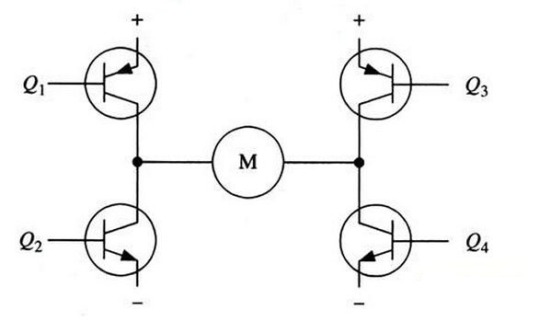
Figure 1. H-bridge Motor Drive Circuit
Figure 1 shows a typical DC motor control circuit. The circuit is name as "H-bridge drive circuit" because its shape resembles the letter H. The four transistors make up the four vertical legs of H, and the motor is the horizontal bar in H.
(Note: Figure 1 and the following two figures are only schematic diagrams, not complete circuit diagrams, and the drive circuit of the transistor is not shown.)
As shown in the figure above, the H-bridge motor drive circuit includes 4 transistors and a motor. To make the motor run, the pair of transistors on the diagonal must be turned on. Depending on the conduction of different transistor pairs, current may flow through the motor from left to right or from right to left to control the veer of the motor.
For example, as shown in Figure 2, when the transistor Q1 and Q4 are turned on, the current passes from the positive electrode of the power supply and the motor from left to right through Q1 , and then returns to the negative electrode of the power supply through Q4. As shown by the current arrow in the figure, the current flowing in this direction will drive the motor to rotate clockwise.
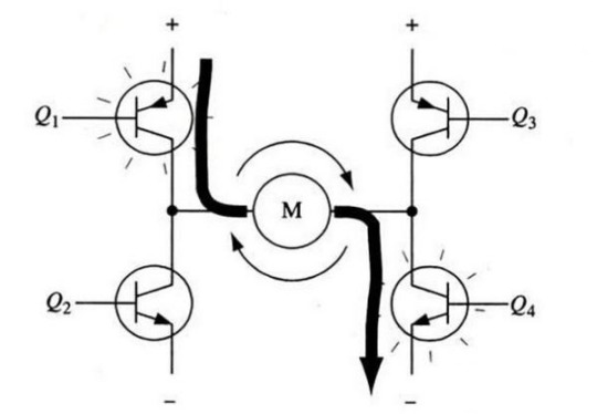
Figure 2 The H-bridge circuit drives the motor to rotate clockwise
When the transistors Q1 and Q4 are turned on, current will flow through the motor from left to right, thereby driving the motor to rotate in a specific direction (the arrows around the motor indicate clockwise direction).
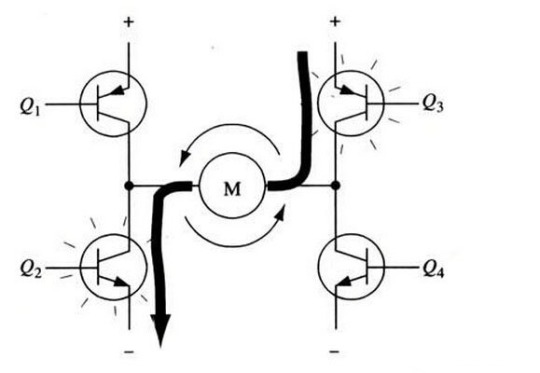
Figure 3 The H-bridge circuit drives the motor to rotate counterclockwise
Figure 3 shows the case where another pair of transistors Q2 and Q3 are conducting, and the current flows from right to left through the motor.
When the transistors Q2 and Q3 are turned on, the current flows from right to left through the motor, thereby driving the motor to rotate in the other direction (the arrow around the motor indicate counterclockwise direction).
Enable Control and Logic Direction
When driving the motor, it is important to ensure that the two transistors on the same side of the H-bridge do not conduct at the same time. If the transistors Q1 and Q2 are turned on at the same time, the current will pass from the positive electrode directly to the negative electrode through the two transistors. At this time, there is no load other than the transistor in the circuit, so the current on the circuit may reach the maximum value (the current is limited only by the performance of the power supply), and the transistor may even be burned out.
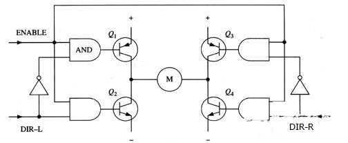
Figure 4 H-bridge Circuit with Enable Control and Direction Logic
Based on the above reasons, in actual drive circuits, it is usually necessary to use hardware circuits to conveniently control the switch of the transistors. Figure 4 shows an improved circuit based on this consideration. We add 4 AND gates and 2 NOT gates to the basic H-bridge circuit. The four AND gates are connected with the same "enable" conduction signal. In this way, the switch of the entire circuit can be controlled by this one signal. The two NOT gates can be used to provide input in one direction, which can ensure that only one transistor on the same leg of the H bridge can be turned on at any time.
(Like the previous diagrams, Figure 4 is not a complete circuit diagram, especially the direct connection of the AND gate and the transistor in the figure does not work properly.)
Using the above method, the operation of the motor only needs to be controlled by three signals: two direction signals and one enable signal. If the DIR-L signal is 0, the DIR-R signal is 1, and the enable signal is 1, then the transistors Q1 and Q4 are turned on, and the current flows from left to right through the motor (as shown in Figure 5); if DIR-L The signal becomes 1, and the DIR-R signal becomes 0, then Q2 and Q3 will be turned on, and the current will flow through the motor in the reverse direction.
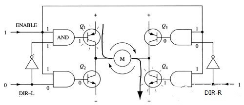
Figure 5 Use of enable signal and direction signal
In actual use, it is very troublesome to make H-bridges with discrete parts. Fortunately, there are many packaged H-bridge integrated circuits on the market. They can be used by connecting power, motors and control signals, which is very convenient and reliable to use under the rated voltage and current. Such as commonly used L293D, L298N, TA7257P, SN754410 and so on.
H-bridge circuit is often used in inverter circuits and DC motor circuits. Here we only explain the application principle of H-bridge circuit in DC motors. I hope that you can fully grasp the basic knowledge of the full-bridge circuit. This will not only facilitate the rapid design, but also help us consolidate the basic knowledge of circuits.
Related Source:
MOSFET Gate Drive Circuit Basics
0 notes
Text
Basic Knowledge about DSP Technology
An article giving you a comprehensive introduction of DSP technology.
Click to read! http://www.kynixsemiconductor.com/News/100.html :)

1 note
·
View note
Text
The Difference Between Polarized And Non-polarized Capacitors
The Difference Between Polarized And Non-polarized Capacitors
The difference in performance and principle structure

Same in principle: (1) They both store and release charges; (2) The voltage on the electrode plate (here, the electromotive force accumulated by the charge is called voltage) cannot be abruptly changed.
The difference lies in the different media, different performance, different capacity, different structures, and different use…
View On WordPress
0 notes
Link
Give you a comprehensive introduction about the solid capacitors. Click to read it!
0 notes
Link
A good article for PCB surface treatment. Click if you’re interested!
1 note
·
View note
Link
0 notes
Link
Some advice for IC judgement. Check it out!
0 notes
Link
Here are some tips for copying PCB board. Check it out if you like! :)
1 note
·
View note
Link
An article introducing some solutions for EMI on single chip systems.
0 notes