
uq-tech-talk
The Trials and Tribulations of Troubleshooting
It's time to cry until things work. Then we can be happy until we need to make the next thing work. Such is life
13 posts
Don't wanna be here? Send us removal request.
Last Seen Blogs

bigerpapi
lovery girls

ray-sussmann
Ray Sussmann

lgwifey
mirrorball

cafegold1905
İsimsiz

violet318
Violet 's Storys
Text
UE5 Post Process
DaVinci Resolve Colour LUT
I have done this once before and it looked hot. That being said, it was a bit of a headache and I don't want to have to research everything again.
Obviously we start by creating a new project in DaVinci and switching over to the Media tab at the bottom of the screen. I dragged in my video file that I want to generate a LUT for into the top left quadrant of the screen. DaVinci doesn't seem to like the avi files Unreal renders in, so I put my video through HandBrake and converted it to a m4v.
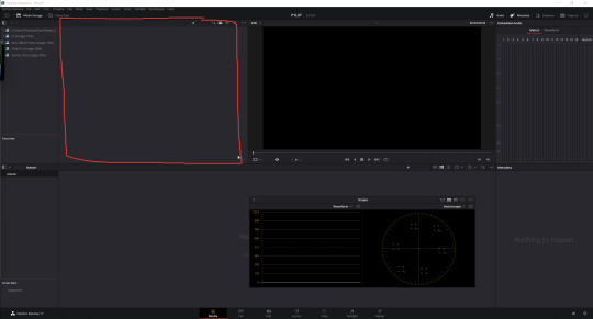
I dragged my video file from the section highlighted above down to the section right below. That is the Media Pool.
Next up, I switched over the the Edit tab at the bottom of the screen and clicked File (top File, Edit, ... ect bar) > New Timeline > named it > Create. Now we can drag the video file from the Media Pool on the left, on to the timeline at the bottom of the screen. My Scopes popout window wasn't there the first time I did this, so I right clicked my video in the viewport and opened Show Scopes
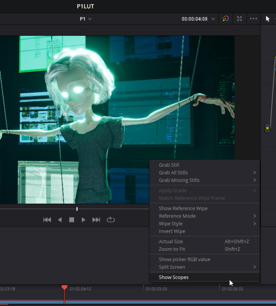
In its popup, we really just need to see the Waveform and the Vectorscope for colour grading. I scrubbed through my video clip and found a good frame where the Waveform isn't crunched on the top or the bottom of its graph. This means that the shot we work with won't be too over/under exposed in areas and there won't be much data loss.
First up, I'm going to adjust the Lift dial. Sliding right will lighten shadows, and sliding left will darken them. Bring the Waveform down so that its very close/just touching the bottom of the graph without squishing its values. Next I adjusted the Gain wheel. Sliding right will increase the contrast and brighten whites, and sliding left will lower it. I brought the gain up as close to the top of the Waveform as I could before it started looking too blown out in the light areas. Now we will have a good range to work with. Now I will adjust the White balance and Temperature by selecting the eyedropper tool right above the lift wheel, and clicking in the whitest area in the viweport. Next up, I adjusted the Gamma to edit the contrast of the mid values. Sliding right will make the mid tones lighter, and left will make them darker. If needed I can do another colour pick and take a new sample for the white balance.
If I click the little number at the bottom of my node on the right side, I can toggle on/off my changes to see a before and after.
The problem with doing a blanket LUT for an entire project is that if your renders have very different levels of exposure, some areas will be too blown out/dark. In that case it would be best to bring each render into DaVinci and colour grade them individually. That is unquestionably what I should be doing in my case but This is due imminently and time is of the essence.
Regardless, scrub through the entire clip and make adjustments so that the whole thing can look as evenly good as possible.
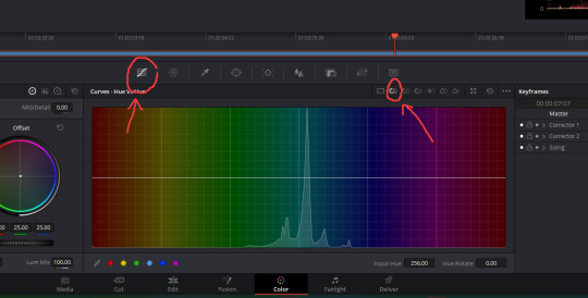
Now it's time to play with colour. I right clicked my node on the right and chose Add Node > In Sequence. This gives us a new node to work with on top of the one we did for the exposure and white balance so that if things turn out badly, we can just delete it without messing up what we did before.
Make sure you are on the Curves tab and the Hue Vs Hue subtab. You can add points along the line and drag out to really pull out the important colours, or to do some widespread tone changes for your entire piece.
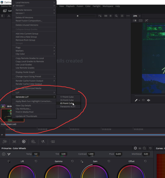
And now we export! Right click your video thumbnail >Generate LUT > 65 Point Cube

The time has come to close DiVinci and open the RGB Table above in Photoshop. I clicked the little lock on the base layer to turn it into a normal one, add an adjustment filter, and in the Adjustments tab select Color Lookup.
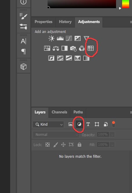
Now I'm clicking the dropdown beside 3DLUT File, choosing Load 3D LUT (first option), and finding my LUT file from DaVinci. All I have left to do here is save the file out as a PNG called ColourGrade.
Back in Unreal, I imported my colour grade png we just made in photoshop into my content browser, opened its texture, searched LOD, changed the Texture Group from World to ColorLookupTable, and saved it. Next I put a PostProcessVolume in my scene, searched color lut in the Details panel, checked off Color GradingLUT, and dragged my color grade texture from my content browser into its slot.
UE5 Sharpen Filter
I already have a Sharpen material uasset, so I'm going to copy it from my file folder and paste it into my unreal project file folder under its appropriate folder in the content. You have to do it this was because unreal doesn't allow you to just drag a foreign uasset straight into its engine.
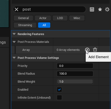
I'm selecting my PostProcessVolume in my outliner again and this time, searching post in the Details panel. Next I added an Array (image below), dropped down the Choose tab, selected Asset Reference, and dragged my sharpen material into the little spot in the array that gets highlighted as soon as I start moving the material.
Your scene will probably look super grainy now, but we can fix that. I opened my sharpen material and adjusted my two Constants in charge of sharpening my edges. Setting them to something like 0.0005 and -0.0005 is a good place to start, and then you can make TINY adjustments if your scene looks too blurred/sharp.
Path Tracer
First thing's first, go to Edit > Project Settings > search RHI > and make sure your Default RHI is set to DirectX 12. You should only have to do this once in order for it to be applied to all of your future projects. Now we need to search raytracing and enable it. If you have the hardware to do so, enable as much raytracing as you can.
Now technically we can use Path Tracer! Rendering each frame in your viweport will take a hot minute so if you want a progress bar to see how close to done it is type r.pathtracing.progressdisplay 1 in the Console Command at the bottom of the screen.
Find your PostProcessVolume in your Outliner again and search path in its Details panel. Turn on Samples Per Pixel and bring it waaaaay down. We're talking like 300. Otherwise, chances are either you or your gpu will have died of old age by the time it finishes rendering.
Here's the sad news. There's a lot of stuff Path Tracer doesn't support
Grooms
Cascade Particles
Splines
Decals
Volumetric Fog
Exponential Heightfog
Light Functions
Hair and Single Layer Water Materials
Multi-GPU support
Depth of field in Post Process
RIP
It makes some sweet glass and lighting bounces but can be pretty useless on projects that need any of those. Hopefully UE5 will have an update soon where they make it more compatible cause when it works, it really is beautiful
#artists on tumblr#art#3d artist#tech#game art#ue5#unreal engine#post processing#davinci resolve#photoshop#color grading
0 notes
Text
UE5 - Stylized Clouds... cough...Bubbles
I am still in the process of creating my axolotl, and have now moved on to giving him a little setting. The model is the main focus so I really just wanted some atmosphere. My idea for this is to surround my pink axolotl with some pink cotton candy-esque clouds and a nice pink sky. My work is typically on the more dark and eerie side so I'm trying a 180 for this to get some variety. The VolumetricCloud system in Unreal is good for some things but is hard when you want a lot more control in the design. I modified my VolumetricClouds as much as I could and as nice atmospheric background, I'm happy. Now I will attempt to handmake individual stylized clouds that are modeled to flow around my axolotl exactly how I want them to.
I started out in ZBush and made three cloud variations, using a sphere as the base and sculpting it. Nothing too fancy. Next I used ZPlugin to UV each cloud, and exported them as FBXs. I dropped my three files into my content browser as StaticMeshes, positioned my clouds around my axolotl, and here... we... go...
First things first, I'm creating a new material called Clouds. When I open its blueprint, I'm going to change its BlendMode to Masked. I connected a nice cotton candy pink Vector3 to the BaseColour node, and created an Emissive parameter set to 0.5 and connected it into the EmissiveColour node. Next I plugged a Fresnel into a DitherTemporalAA's AlphaThreshold, and plugged the the DitherTemporalAA's output into the OpacityMask node. I plugged a constant that I left at 0 for now into the DitherTemporalAA's Random node, and put a clamp between the Fresnel and the DitherTemporalAA with the Min default set to 0.5 and leaving the Max at 1.0. Next I'm putting a 1-x node between the Fresnel and the Clamp so that the transparency is just around the edges, and set the Fresnel Exponent to 2.
Since I enabled starter content when I created my project, I'm bringing in a water normal map and plugging it into a Multiply set to 0.3, and plugging the Multiply's output into the material's Normal. I applied the material to my clouds and to be honest, I don't think its exactly the look I'm going for. It is extremely stylized almost to the point of comic book aesthetic. I really like how they look, but I don't think they totally fit with what I want for this project.
So I spent the last three hours researching and testing out ideas and I think I can make this work.
It's the DitherTemporalAA thats causing the grainy comic book style pixilation, and sadly I don't think there is currently any better option. So we work with what we've got.
I started by connecting the Fresnel's output straight into the Clamp's input and deleting the 1-x math node that was between them. I changed the Fresnel's exponent value to 1, and changed the Clamp's MinDefault to 0.2. Next I plugged a TextureCoordinate into a Panner with the X and Y Speeds set to 0.05, then plugged the Panner's output into the TextureSample's (normal map) UVs. Now she's moving.
What I wanted to do was use tessellation and world displacement to fake deformation with another panner but for whatever reason they're both unsupported in UE5. Most people seemed to be saying 5 has made them obsolete because of nanite but I don't think (and I could be wrong) that nanite can help me in this situation.
I ended up duplicating the entire string I created to put in the Material's Normal, and plugging the duplicate's multiply node output into the Material's WorldPositionOffset. I changed the Panner's X and Y speeds to 0.1, and the Multiply's ConstantB to 5. Now it's time to open the champagne because this hot thing wiggles.
They look more like bubbles now and honestly, I think that works better. I'm going to give them a little looping animation in Maya that will really stretch the mesh now. With the normal and slight edge deformation in the material on top of an animated model, I do believe we will have some attractive bubbles.
#artists on tumblr#art#3d artist#modelling#learning#tech#programming#game art#autodeskmaya#rigging#axolotl#ue5#unreal engine#animation
0 notes
Text
Rigging an Axolotl - Weights and Animation to UE5
So I had this whole thing written and then I was an idiot and forgot to duplicate the maya file and delete all the stuff I didn't need so it wouldn't be painfully slow. RIP
Basically after deleting everything's history and freezing transformations, I selected all the components of the mesh, selected the root joint of the skeleton (hips), and went to Skin>Bind Skin options>set to Joint Hierarchy, Geodesic Voxel, Dual Quaternion, Interactive, Distance, checked off Allow Multiple Bind Poses, set Max influence to 5>Apply and Close. Now when I rotate the joints, the mesh will move accordingly.
I exported the whole thing as a single fbx and brought it into UE5 to make sure it worked and it was all good. For now though, I'm going to focus on getting the weight painting sorted out in maya.
I'm going to start with the neck by rotating to joint until I start to see some janky deformation happening, then I selected the piece of mesh effected, and then I dropped down Skin>and opened the Weight Painting options box. In the popup, I selected the neck joint.
To make it easier to see what I'm painting I'm switching to a split screen viewport, with both of them in perspective but one with Selection Highlighting turned off in the Show dropdown. Now we paint.
When I was happy with the weights, I gave it a little animation at 30fps. Idk if importing with a specific framerate is necessary but I know that the unreal cinematic default framerate is 30.
Now we can leave maya! I selected all the components of my axolotl mesh and rig, and exported it as a single fbx. I dropped the one fbx file into my content browser in UE5 and made sure it was going to import it as skeletal mesh and that include animations were turned on. Now I have a SkeletalMesh, PhysicsAsset, and AnimationSequence made out of my single fbx. If I open the AnimationSequence, it should play properly. All that's left now is to texture him like normal and set up a little environment!
#artists on tumblr#art#3d artist#modelling#learning#tech#programming#game art#autodeskmaya#rigging#axolotl#ue5#unreal engine#animation
1 note
·
View note
Text
Rigging an Axolotl
I would like to preface this by saying that I absolutely suck at rigs. In the spirit of full transparency, I have never successfully brought my own rig with animation attached from maya to unreal. So this is gonna be a trip. Hopefully we get to the destination.
I brought my low poly model (it's not really very low poly though... thank you nanite...), froze its transformation, deleted its history and switched over to a rigging workspace. I dumped all the components of my model into a layer that I set to R so I wouldn't accidentally select the mesh when dealing with joints. It's usually easiest to rig in wireframe (4 on keyboard), and with X-Ray Joints turned on in the viewport's shading tab. Next I went to Skeleton>CreateJoints options>reset the settings and turned on Orient Joints to World.
And now we begin! Starting at the hips I created joints upwards into the head. If the joints are too little you can go to Display>Animation>JointSize>and mess with the scaler.
Starting at their base, I'm going to do his little head frills one at a time but not connect them to the head joint just yet.
I ended up having to adjust the positioning of all the joints using the move tool after because my model is already posed and very unsymmetrical.
Now that the joints are all positioned nicely inside the mesh, I'm going to do the same thing for the arms, legs, and tail, still starting at the limb's base but not connecting anything to the root spine yet.
Alright, all the joints have been created and now we have the fun task of naming them all :') This is something that your future self will appreciate. Not your present self though. Your present self will want death.
The time has now come to parent all the joint strings! I select the root joint of the child, then select the joint I want to connect it to, and hit p on the keyboard. Everything is connected and life is good. We will see how things go tomorrow
#artists on tumblr#art#3d artist#modelling#learning#tech#programming#game art#autodeskmaya#rigging#axolotl
0 notes
Text
UE5 Hair Shader - Anisotropic hair? Nani?
Alright so this is going to be a new experience. I used FiberMesh in Zbrush to make the hair for my character and because I enjoy tempting fate nothing has been converted to hair cards. I'd say god bless nanite for this one but I actually had to disable it for the hair because as I zoomed out, it made my model bald. We are not going for the egg look today.
The second thing that might make this go horribly wrong is the fact that none of the hair fibers are UVed. The poly count for them is 3.5 million and I don't have the emotional capacity to console my PC later.
Ok Lets A Go! I'm going to start out by making a new material called M_Hair. I created a colour parameter by holding v and clicking, and named it Hair Root Colour. I duplicated it and edited the name to be Hair Tip Colour. Next I created a Lerp node, plugged the RGBA of the root colour into the A, and the RGBA of the tip colour into the B.
Now I'm going to create a TextureCoordinate node that will plug into a ComponentMask node with only its G channel turned on. The component mask will then plug into the Alpha of the Lerp, and the output of the Lerp will plug into the material's Base Colour. I set the root colour to pure black, and the tip colour to a dark-ish grey and changed the viewing model to a plane to see a nice gradation.
Next I will select the material node and change its material Shading Mode to Hair. I'm going to made a Vector3, set the colour to pure green (G=1), and plug it into the Tangent on the material. Now I'm creating a parameter, naming it Scatter, setting its Default Value to 1, its Slider Max to 1, and plugging it into the Scatter node of the material. I made another parameter, called this one Roughness, set its Default Value to 0.3, the Slider Max to 1, and plugged it into the material's Roughness node. One last time. I'm making another parameter, naming this one Specular, setting its Default Value to 1, its Slider Max to 1, and plugging it into the material's Specular node. Now we can close the material editor, and create a material instance out of the hair material we just made.
I ended up having to go back into the material because for a reason my little brain couldn't figure out, the material came out a wonky black. There were shines where there shouldn't have been and there was no colour gradation. This probably isn't the right way to deal with this but I unplugged the Hair Tip Colour RGBA and plugged it into the Lerp's A, and unplugged the Hair Root Colour RGBA and plugged it into the the Lerp's B.
Ok scratch that, I think I got it. I deleted the material instance and tried just putting my base hair material right on my model and things seem to be working better now. First of all, put your root and tip RGBAs back into their proper Lerp nodes. Next I edited the root colour to be a nice dark grey, and the tip colour to be almost white. Now if I look at the material preview on a plane, it will be a metallic gradation with the top being darker and the bottom being slightly lighter. And now it's just a matter of messing with the Scatter, Specular, and Roughness Default Values to get it to your liking.
If I had a normal map for the hair I'd blend it with the Vector3 plugged into the tangent, but I think for my current project, that would be overkill. I'm also wondering what would happen if I wanted coloured hair instead of black and white.
Biiiiiiiiiiiiiiig brain. Huuuuuuuuuuuuuuge brain. I created another Vector3 set it to a nice off white (kinda beige) colour, created a BlendScreen node, plugged the beige Vec3 into its Blend node, plugged the Lerp output into its Base node, and plugged the Result into the material Base Colour and would you look at that... it's hair.
#artists on tumblr#art#3d artist#ue5#modelling#learning#tech#programming#game art#unreal engine#hair systems
0 notes
Text
Zbrush - Loose Curl FiberMesh Hair
Turn on symmetry and PolyFill for the head subtool, and using the SelectLasso with ctrl and shift, mask off the scalp and hit ctrl w to give it its own polygroup. Turn off symmetry and use SelectLasso to slice the head roughly down the center (two halves now), ctrl w to give it a separate group, then ctrl shift click anywhere outside to make everything visible again. Switch to SelectRect and click one of the halves to solo it and repeat this process of division until we're satisfied with the number of clumps. Make sure you do this on both sides. That would be a sad mistake.
SADGE apparently you can ctrl shift alt to get rid of the chunks instead of having to switch to the SelectRect tool.
Select the face polygroup and inverse the selection to now only the polygroups for the scalp are visible. Ctrl and click outside to mask off the entire scalp, then ctrl shift and click outside to bring back all the other pieces. Drop down the Masking tab in the Tools bar and ShrinkMask 2(ish) times, then SharpenMask.
Open the FiberMesh tab in the Tools tab and click LightboxFibers. Select Fibers142 and open the Modifiers tab. Set Gravity to -1, remove the texture file, turn NoV, HtV, VtV, and ClV down to 0, set Coverage to something like 10, set MaxFibers to something like 8, set the Length to whatever I want, set Segments to something around 25, hit Accept and say Yes. To the dress. Nvm.
With the SelectRect tool as the one assigned to ctrl shift, use the GroomHairBall tool and ball up each polygroups hair so her head is covered in little knots. Solo one of the knots at the base of her neck and snap to orthographic bottom view. Using the GroomTwister brush (make it very big). drag out slowly until you get a shape that looks like a comma, then without releasing the mouse, drag back into the center to create a nice curl. Hit w to pull up the transform tool and hit y to change it to line mode. Center it in the curl and while holding shift, drag the middle circle down to unfold the curl. Repeat this for all of them while crying.
#artists on tumblr#art#3d artist#ue5#modelling#learning#tech#programming#game art#unreal engine#zbrush#character modeling
1 note
·
View note
Text
ZBrush Notes
Recenter pivot without moving subtool:
Turn off any symmetry, hit w to pull up the transform tool, unlock the lock, hit reset orientation, and hit go to unmasked mesh center
Duplicate mesh within a subtool:
Hit w to pull up the transform tool, and hold ctrl while moving the mesh and it will move a copy without creating a new subtool for it
Select duplicated meshes/appends withing a single subtool:
Hit w to pull up the transform tool, and hold ctrl and shift while dragging a little anywhere on the object you want masked. We can now manipulate it without it affecting the other pieces in its subtool
Delete hidden masked section:
Mask off the area you want removed, turn on Poly Fill and hit ctrl w to create a separate polygroup for the masked area, ctrl and click on the polygroup you dont want deleted so only it is visible, then in the Tools tab, open Geometry > Modify Topology > Del Hidden
Mirror mesh/subtool:
Make sure the part you want mirrored is on the right side of your model (otherwise you need to flip the model first), then go to the Geometry tab > Modify Topology > Mirror And Weld
#artists on tumblr#art#3d artist#ue5#modelling#learning#tech#programming#game art#unreal engine#zbrush
2 notes
·
View notes
Text
UE5 Fabric Tear Alpha - Making Things Move ... Hopefully
I am determined to get this today. Everything is set up and Unreal has been opened. I'm opening up the canopy's Skeletal Mesh and the clothing data tab in its popup (window > clothing data), making sure Section Selection above the little viewport is active, selecting the rips and right clicking, choosing create clothing data, right clicking the rips again, and choosing apply the clothing data I just created. The shaders just finished compiling and now I have some video previewing tools in the bottom right. Up at the top, I'm turning on Activate Cloth Paint and selecting the Clothing Data in the Clothing tab. The areas I assigned as the rips have all turned pink and my mouse has switched to a brush. Mistakes were made, I should have added caps to my discs. The brush tool appears to use vertex painting and with my discs shaped like wonky pie, its not going to work. I have to head back over to maya and add more divisions. Sadge.
So I added rings inside each disk and re-exported the model but when I reloaded it in Unreal and tried to assign it cloth again, I got this lovely error

I ended up reverting the maya file back to when there were no rings, tried it again and it worked. Thank god. But I really do want those extra vertices. So I'm hopping between Maya and UE5 right now adding rings to one hole, exporting, testing, then doing the next. It seems to be working so far. I'm hoping that this way I can figure out exactly where the issue is.
All of the large and medium holes pass Unreal's vibe check and to be perfectly honest, I really don't care about extra vertices on the tiny ones. They're so small the wind wouldn't effect them anyway.
I deleted, recreated, and reassigned the cloth, and activated Cloth Paint one last time and it looks like it should be good to go.
In the Cloth Painting Properties tab, I set the View Max to 100, the paint value to 100 and adjusted the brush radius, falloff, and strength depending on the side and shape of the hole.
I would like to thank the academy, it works.
The time has come to drop the canopy Skeletal Mesh back into my scene. I'm going to hit simulate to see in real-time, search in the Place Actors tab for Wind and bring in a Wind Directional Source, and play with the speed until I like how the fabric reacts.
I learned a lot making this and though there are definitely things I will do differently next time, but overall I'm super happy with how it turned out.
1 note
·
View note
Text
UE5 Fabric Tear Alpha - Fixing Edges with Cloth Physics
Alright we have some hot rips now. I ended up taking the UV snapshot of the whole canopy and hand painting the torn fabric. All we really need are the holes though so I hid the layers for everything else, dumped in a black background, exported the colour and opacity masks, generated a normal map, brought them into Unreal, and assigned them to the disc filling the hole. It looks glorious. I might go back to Photoshop and adjust the colours a bit, but right now I just want to see if I can get this to work. Before I start dealing with the physics, I do need to bloop back over to Maya and fill the rest of the holes with planes.
The holes are filled and tomorrow I will test the physics. Sleep is needed.
0 notes
Text
UE5 Fabric Tear Alpha - Static Edges with Moving Centre
It's a new day and I feel like I can get this cloth figured out. I hopped into Maya and filled one of the holes to test my plan, assigned it its own material and re-exported the canopy mesh. When I replaced the FBX in my Unreal scene it came in perfectly, keeping my nice canopy material and having the hole display the default grid texture. I'm going to try replacing the plane from yesterday in the blueprint with the canopy mesh and see what happens. This is uncharted waters we've entered. Partial success, I assigned the materials backwards but that's an easy fix, however the bigger issue is that it looks like the edges wont say connected to the mesh even though it's one piece.
Update: Things are not ok. Not even a little bit. I would like to start a new life as a sheep farmer. I have no idea how to fix this.
When all else fails, start deleting. I don't think that's a good suggestion but we're doing it anyway. I force deleted the entire canopy mesh and am reimporting it, but this time as a Skeletal Mesh and I clicked Import. We have a Skeletal Mesh, a Physics Asset. a Skeleton, and two materials. I've opened up the material assigned to the canopy and plugged in its texture files. There is already a material I made for it in another folder but we're starting clean. Now I'm going to go into the other material and bring in the rip texture, set it to two sided, change the material's Blend Mode to Masked, create a quick opacity mask in photoshop by taking my colour map and making all areas that I want transparent black and everything I want to show white. I plugged the colour and normal maps in like usual and then plugged the RGB of the opacity mask into the base material's Opacity Mask node. Success.
Creating a basic rip texture was a mistake. I should have coustomized it to fit the hole as the hole is a very specific shape. I think I'm going to have to hop back into Photoshop now are redo the rip texture using a UV Snapshot from Maya. Sadge
1 note
·
View note
Text
UE5 Fabric Tear Alpha - Positioning in Scene
Well I'm an idiot. The blueprint does work, its pivot just isn't attached and I didn't see that it comes in at world 0 no matter where you drop the little blueprint icon or move it to. I'm not sure why that is or how to fix it yet but at least it works. It also added the wind effect to the edges which does not make me happy.
Wrinkly brain ftw!!! I went back into the blueprint and realized that the SplineMesh wasn't the child of the Spline. Note for future me when I turn this into a clean set of instructions, the components are parented as follows:
DefaultSceneRoot > Scene > Spline > SplineMesh
Now to take a look at those wiggly edges. No one needs wiggly edges.
I have an idea but it will take time. I'm hopping back into maya and filling the holes in my model's canopy that I want to put the stringy fabric in with a disc. I think I'll do a planier UV, assign it it's own material and tomorrow I can bring the updated FBX canopy file into Unreal and set the entire piece as my mesh, and the disk for the material, instead of using the bent plane. But that is definitely a problem for future me.
1 note
·
View note
Text
UE5 Fabric Tear Alpha - Attempting to Apply the Material
The process of creating the material seemed a bit too easy and I'm spamming X. I've got a feeling that this part wont be very nice but we're here now. Before I get too far into things, I do want to see how the cloth strings would look with some normals. This could be a very bad idea but I'm tired and really don't care.
So I think that looks alright? It could be a case of 'feeling cute might delete later' but for now the normal map stays.
I'm going to create a blueprint actor and call it FabricStrings, and because we keep things tidy here ... ha.. haha... ha.. no... it gets its own little blueprint folder. A nice man on YouTube said to add a Scene component and then a Spline component. In the spirit of honesty, I have no idea where this is going but I'm putting all my faith in him. Please don't let me down friend. We're blooping over to the Construction Script tab now and are going to drag in the spline and hit get.
Lies and deceit, there was no get option, it just popped in. Slightly concerning but I will venture on. I dragged out the node from the spline and searched Get Number of Spline Points, then I dragged out the node from the Construction Script and searched For Loop. The guy says the next step is to drag out the Return Value of the Get Number of Spline Points node and search (int-int) but nothing is coming up. I have a feeling that its just a regular math node and there's only one way to find out. It has now been plugged into a subtract node. Chaos may ensue. I changed the value of subtraction to two and plugged its output into the Last Index of the For Loop node.
To Maya! I feel like we could probably just do this in Unreal but that sounds like additional stress and lord knows I don't need any more. I made a plane, scaled it up, changed the subdivisions to 2 and 2 (it looks like a four square board now), selected the three vertices running down the middle, moved them down a TINY bit, then set the pivot to one of the outer middle bent vertices. Export that guy as an FBX and bring it into Unreal.
I'm adding another component, SplineMesh, and over in the Static Mesh section in the Details panel, I'm assigning the plane I just created.
I think this next bit is going to made some nice things happen. If I double click the little mesh image preview in the Static Mesh section in the Details panel, we should be able to assign it the FabricStrings material ANNNNNNNNNND... nothing happened. Sadge. We're going to pretend it worked and hope this was meant to happen.
Time to return to the Construction Script. I'm dragging the SplineMesh in from the Components section and dragging its output to search AttachComponentToComponent. I'm also going to drag the Scene in from the Components section and plug its output into the parent node of the AttachComponentToComponent. We should be able to drag out another connection from the Spline Mesh output to search for SetStartAndEnd. The Exec out pin on the AttatchComponentToComponent should plug into the Exec pin on the SetStartAndEnd.
I'm bringing in a Spline from the Components section and dragging its output to search GetLocationAndTangentAtSplinePoint. Booping back over to the ForLoop node, I think we should plug the Index into the Point Index of the GetLocationAndTangentAtSplinePoint, then connect its Location pin to the Start Pos of the SetStartAndEnd node.
We're going to duplicate the GetLocationAndTangentAtSplinePoint node and plug the Spline into its Target. Drag another connection out from the ForLoop node and search Add. I'm connecting the Add output to the Point Index of the new GetLocationAndTangentAtSplinePoint and then finishing it off by connecting its Location to the End Pos of the SetStartAndEnd node. Lets compile and try bringing the blueprint into the scene.
And it didn't work. I would like to remove my kneecaps with a spoon.
1 note
·
View note
Text
UE5 Fabric Tear Alpha - Figuring Stuff Out
Alright, so I've made cobwebs before and I feel like this should be a very similar process. That being said, it's been a long time and the engine updated so there could be some previously unencountered issues. We shall see.
It is surprisingly difficult to find a nice image of ripped cloth. I guess it's not a popular image search. The file is is Photoshop and I removed the background, pixel locked the layer and painted it until I didn't hate it. I'm going to extend the top and bottom using the clone stamp tool to try and make it a square file. I have a funny feeling Unreal will appreciate that.
Moving into engine, I created a new material named FabricStrings_Parent and opened its blueprint. Standard stuff so far, dragged in the colour map, plugged the RGB into the material base colour, and now things should get a little funky. I created an Add node, plugged the texture's RGB into the A and the output of the Add node into the greyed out Opacity Mask of the base material.
Next is to fix our hot mess. Hopefully. I clicked the material and changed the Blend Mode in the Details panel to Masked. Next I selected the Add node and set the Constant B to 0.3. Success! We have transparency. I'm going to throw in a constant for roughness and set it to 0.8. I think that will look nice.
Now things should get fun. I added a SimpleGrassWind node and plugged four constants into its four inputs. We're just going to throw in some numbers right now and pray. I set the WindIntensity to 1, the WindWeight to 0.3, the currently greyed out (hoping that's not going to be an issue) WindSpeedto 0.2, and the AdditionalWPO to 0.2 as well. I think everything is set and the time has come to cross all fingers and toes that this works. I'm going to plug the result into the material's World Position Offset.
Happy happy days, it works. there is too much distortion happening on the edges but I think I can fix that. Now that the animated material works, I believe the next step will be figuring out how to apply it while maintaining its outer shape.
2 notes
·
View notes