#NXOpen
Text
Siemens NX 二次開發環境設定範例
之前介紹了Siemens NX 2206 的基本操作,
還有簡易的草圖繪製範例,
這些都是 CAD基礎,
今天要來點不一樣地,
這次要教大家
Siemens NX 二次開發環境設定範例
Siemens NX 提供了NXOpen、UGOpen、BlockUi、GRIP等API,
讓開發者能夠使用C#、C++、Python等語言,
依照需求開發自已的應用程式,
在開發之前最重要的就是環境建置,
首先要先安裝 NX ,
之後安裝 Visual Studio 2019 。
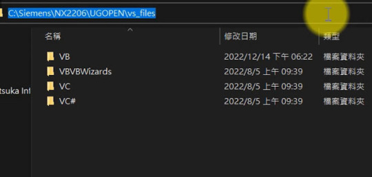
接著在NX安裝資料夾中找到 UGOPEN\vs_files,
這個資料夾中放置了 NX對 Visual Studio 的各語言的範本,
將其複製到 Visual Studio 2019的資料夾中,
由於此處範例僅使用 C# 故僅複製相關的資料夾即可
接著到 Visual Stuio2019的…
View On WordPress
0 notes
Text
What is unigraphics nx

WHAT IS UNIGRAPHICS NX SOFTWARE
WHAT IS UNIGRAPHICS NX PC
WHAT IS UNIGRAPHICS NX FREE
NX. We will explore their histories, capabilities, and users, before going through a direct “CATIA vs….CATIA vs. NX delivers the next generation of design, simulation, and manufacturing solutions that enable companies to realize the value of the digital twin.
WHAT IS UNIGRAPHICS NX SOFTWARE
In this article, we will be comparing two multidisciplinary CAD software giants, CATIA, and NX. Toyota Motor Corporation adopts Two-CAD Strategy with CATIA V5 from Dassault Systèmes and Creo Parametric (Pro/ENGINEER) from PTC as the main CAD systems for product development.16 fév.
WHAT IS UNIGRAPHICS NX PC
SOLIDWORKS eats so much RAM and VRAM to run smoothly, It needs your PC to be expensive (a Workstation), on the other hand NX costs you more purchasing amount than SOLIDWORKS but can run on even an average gaming PC too. Simply put, NX is far deep in terms of designing options availability than SOLIDWORKS.
WHAT IS UNIGRAPHICS NX FREE
NX is available free to any active student for academic course work. Engineering analysis (static, dynamic, electro-magnetic, thermal, using the Finite Element Method, and fluid using the finite volume method). You can open a great variaty of file formats. Unigraphics NX (also known as Siemens nx) is an advanced High-end CAD/CAM/CAE software package originally developed by UGS Corporation, But since 2007 it is owned by Siemens PLM Software. It is very easy to learn design in NX when you have some CAD software background. What is a draft analysis tool in SW and what is it used for 2 answers 966 views 0 followers Is it possible to create a sketch or feature and suppress it, and use it as a point to constrain in the assembly. The languages supported by the NXOpen interface are C++, VB.NET, C# and Java. NX Unigraphics: Tags: unigraphics: Similar questions. This interface is the Siemens NX Common API, in which the developer can choose the language he/she creates the programme in. NX programmes are now generally programmed in the NXOpen interface. In 2000, Unigraphics purchased SDRC I-DEAS and began an effort to integrate aspects of both software packages into a single product which became Unigraphics NX or NX. NX, formerly known as “unigraphics”, is an advanced high-end CAD/CAM/CAE, which has been owned since 2007 by Siemens PLM Software. NX delivers the next generation of design, simulation, and manufacturing solutions that enable companies to realize the value of the digital twin. Siemens NX software is a flexible and powerful integrated solution that helps you deliver better products faster and more efficiently. 10 Which CAD software is used by Toyota?.
0 notes
Text
Employment as an Software Developer at the Longterm Technology Services Inc. London
Employment as an Software Developer at the Longterm Technology Services Inc. London
Preview Longterm Technology Services Inc. With over 20 years of UG/NX experience in the automotive mold and tooling industries, we are an independent consulting firm and Siemens… Location: London – ON – CA Summary Responsibilities & Duties * Develop, modify, integrate and test code for software products, including the motion simulation project, Siemens NXOpen programs, Microsoft Azure Web…
View On WordPress
0 notes
Text
Mapping Polygon Faces to CAD Faces within a NXOpen framework
Quick Overview
This Tips & Trick shows how to map Polygon Faces (i.e., CAE faces) to CAD Faces. Given a CAD Face in the Modeling application, what is its corresponding CAE Face in the Advanced Simulation application ?
Core content
How to find the corresponding CAE Face for a given CAD Face ? Visually, it is obvious to make the match in most cases. For example, Figure 1 shows three (3) faces of a cube in the Modeling application (in a PART file) and their corresponding CAE faces in the FEM part. Equivalent faces share the same color.
However, when writing a NXOpen script, the user does not see the geometry. Therefore, making the match between CAD Faces and CAE Faces is not straightforward. How can we proceed ?
The case of bodies
Matching bodies in NXOpen is easier that matching faces. Indeed, there exist Open C functions that provide the polygon body that corresponds to a given solid / sheet CAD body, and vice versa. These functions are:
1. int UF_SF_modl_body_ask_body (tag_t CAD_body, tag_p_t cae_body )
Input: the CAD body. It can be a solid or a sheet body.
Output: the CAE (polygon) body.
2. int UF_SF_body_ask_modl_body (tag_t CAE Body, tag_p_t CAD Body )
Input: the CAE (polygon) body. It can be a solid or a sheet body.
Ouput: the CAD body.
The first function takes as input the tag of the CAD Body and returns the tag of the corresponding CAE Body. The second function takes as input the tag of the CAE Body and returns the tag of the corresponding CAD Body.
Unfortunately, there are no such functions for CAD and CAE Faces. A different and less explicit approach should be used.
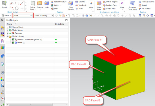

Figure 1: Three (3) CAD Faces of a cube (TOP figure) and their corresponding Polygon Faces (BOTTOM figure).
The power of attributes
Attributes of NX Objects are automatically transferred from PART to FEM (the inverse is not true !). For example, if an attribute is set to a CAD Face, the equivalent CAE Face will inherit the same attribute. To set manually an attribute in NX, right-click on the desired NX Object, go to “Properties“ and select the “Attributes” tab.
Figure 2 shows the attributes dialog of Face # 3. We have created a string attribute with the title “HELLO” and the value “FACE”.
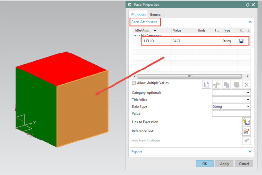
Figure 2: Setting an attribute for CAD Face # 3
Then we go to the FEM and open the attributes dialog for Polygon Face # 3. The polygon face inherits the attribute of its corresponding CAD face, as shown in Figure 3.
Mapping Polygon Faces to CAD Faces by using attributes.
After what has been discussed above, mapping between Polygon Faces and CAD Faces can be done using the following steps:
1. In the PART, loop over all CAD bodies using the Body Collection.
2. For each Body, get all the CAD Faces using the function GetFaces().
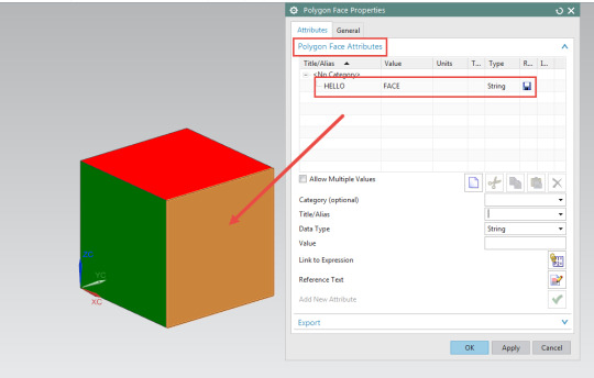
Figure 3: Attributes dialog for the Polygon Face # 3. The attributes are inherited from CAD Face # 3.
3. Loop over all the CAD Faces and for each, set a unique attribute using the function SetAttribute(). The attribute should be unique for each face. For example, set an attribute with title = “ID” and value = “FACE_1” for the first face and another attribute with title = “ID” and value = “FACE_2” for the second face.
4. Create a map that stores all the pairs (FACE, ID).
5. Go to the FEM.
6. Loop over all Polygon bodies using the function UF_SF_ask_all_polygon_bodies().
7. For each Polygon Body, get all the Polygon faces using the function UF_SF_body_ask_faces().
8. For each Polygon Face, read the attribute “ID” using the function GetUserAttribute().
9. Using the map created in step 4, find the corresponding CAD Face.
0 notes
Last Seen Blogs

moonstruckmutt
ARF

sendme-2hell
Where Is Duty? Where Is Sacrifice?
need-ports
Daily Amazing Ports

macellocosmico
macello cosmico.

hylianghoulart
Hylian Ghoul Art