
Last Seen Blogs
avcilarturbanlihatun-blog
TURBANLIHATUN

petrus58
Senza titolo

onemission99
Untitled

mollycoddle
Tassie Mollisons

siberiantrap
nature abhors a binary
Text
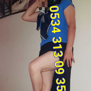
Isometricos 2
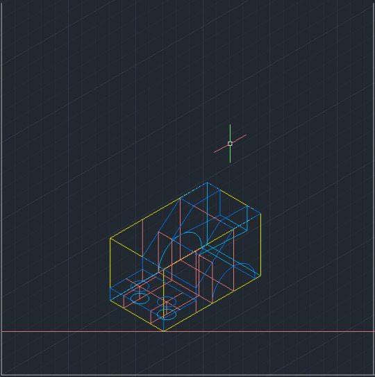
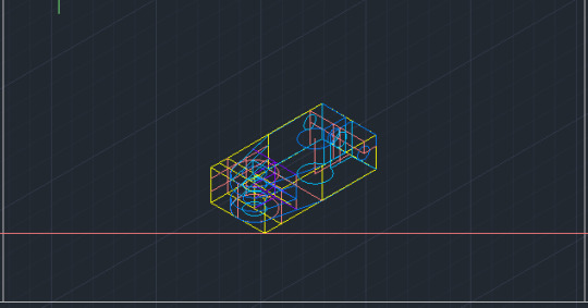
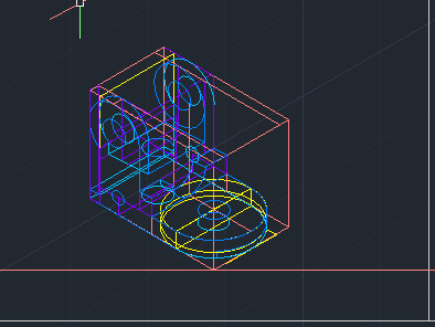
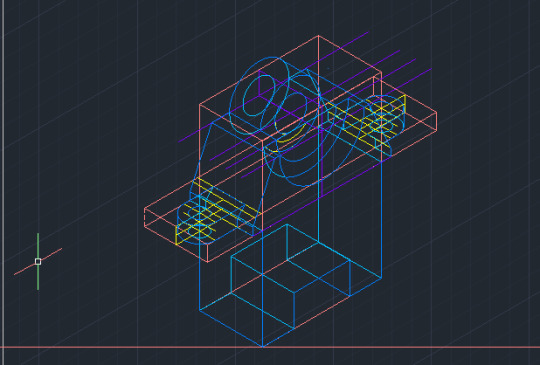
Esta semana realice 5 ejercicios de Isometrias en Autocad, me tomo todo el fin de semana acabar los primeros 2 y del Lunes al Jueves le avance lentamente a los ultimos 2.
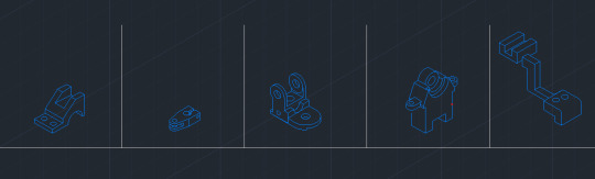
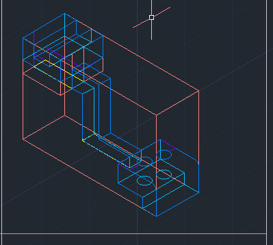
Este es el resultado de mis 5 Isometrias, fue mucho mas dificil de lo que pense pero estoy contento con el resultado
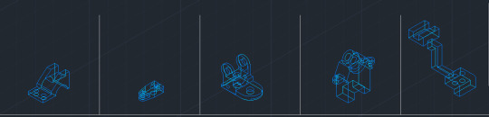
Una vista con mayor detalles de las figuras 3D
Una vista donde se aprecia mejor el gran numero de referencias que me fueron necesarias
0 notes
Text
Ejercicios usando Isometrias
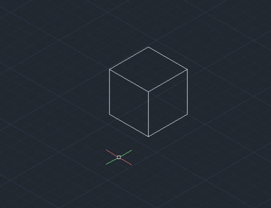
1: Este fue mi primer ejercicio, un cubo
2: Para el segundo se subió la dificultad con varias vistas
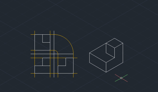
3: El tercero me fue incluso mas sencillo que el anterior ya habiendo practicado y conociendo los comandos

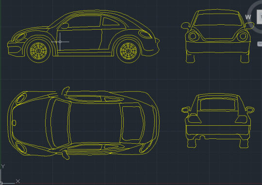
4: Este sin duda el mas difícil, el uso de elipses es complicado aun para mi

0 notes
Text
Comandos 4
DTEXT
Centers the text both horizontally and vertically at the middle of the text. Available for horizontally oriented text only.
The MC option differs from the Middle option in that it uses the midpoint of the height of uppercase letters. The Middle option uses the midpoint of all text, including descenders.
MR (Middle Right)
Right-justifies text at a point specified for the middle of the text. Available for horizontally oriented text only.
BL (Bottom Left)
Left-justifies text at a point specified for the baseline. Available for horizontally oriented text only.
BC (Bottom Center)
Centers text at a point specified for the baseline. Available for horizontally oriented text only.
BR (Bottom Right)
Right-justifies text at a point specified for the baseline. Available for horizontally oriented text only.
Style
Specifies the text style, which determines the appearance of the text characters. Text you create uses the current text style.
Entering ? lists the current text styles, associated font files, height, and other parameters.
ATTACH
Displays a bitmap of the selected file when you choose Views Preview in the dialog box. To save a bitmap with a drawing file, use the Save a Thumbnail Preview Image option on the Open and Save tab in the Options dialog box.
File Name
Displays the name of the file you select in the Files list. If you select multiple files, File Name displays each selected file within quotation marks. You must use quotation marks when entering multiple file names. You can use wild-card characters to filter files displayed in the Files list. For information on wild-card searches, see Wild-Card Characters Reference.
Files of Type
When you are saving files, Files of Type specifies the format in which the file is saved.
Select Initial View
Displays the specified model space view when you open the drawing if the drawing contains more than one named view.
Update Sheet and View Thumbnails Now
Reflects the current setting of the UPDATETHUMBNAIL system variable. This option temporarily overrides, but does not change the current setting of UPDATETHUMBNAIL.
Open/Save
Depending on the purpose of the specific file selection dialog box, opens or saves the selected file or enters the path of the selected folder in the previous dialog box. Certain file selection dialog boxes may include additional options, accessed by clicking the arrow next to the Open button.
Open Read-Only
Opens a file in read-only mode. You cannot save changes to the file using the original file name.
Partial Open (not available in AutoCAD LT)
Displays the Partial Open dialog box. You can open and load a portion of a drawing, including geometry on a specific view or layer. The PARTIALOPEN command can be used only for drawings in AutoCAD 2004 or later format.
Partial Open Read-Only (not available in AutoCAD LT)
Opens the specified drawing portions in read-only mode.
PASTESPEC
Pastes objects from the Clipboard into the current drawing and controls the format of the data.
Find
The Paste Special dialog box is displayed.
PURGE
Removes unused named objects, such as block definitions and layers, from the drawing using the command line.
Summary
Removes unused named objects from a drawing at the Command prompt. You can only remove one level of reference at a time. Repeat the command until there are no unreferenced, named objects.
Note: The PURGE command will not remove unnamed objects (zero-length geometry or empty text and mtext objects) from blocks or locked layers.
List of Prompts
The following prompts are displayed.
Type of Unused Objects to Purge
You can specify what types of named objects that you want to remove, including blocks, detail view styles, dimension styles, groups, layers, linetypes, materials, multileader styles, plot styles, shapes, text styles, multiline styles, section view styles, table styles, visual styles, registered applications, zero-length geometry, empty text objects, and obsolete DGN linestyle data (orphaned data), or all of these.
Enter Name (s) to Purge
Enter an object name of * to list the objects.
Verify Each Name to Be Purged?
Enter y to verify each name.
SPLINE
Creates a smooth curve that passes through or near a set of fit points, or that is defined by the vertices in a control frame.
Find
SPLINE creates curves called nonuniform rational B-splines (NURBS), referred to as splines for simplicity.
Splines are defined either with fit points, or with control vertices. By default, fit points coincide with the spline, while control vertices define a control frame. Control frames provide a convenient method to shape the spline. Each method has its advantages.
To display or hide the control vertices and control frame, select or deselect the spline, or use CVSHOW and CVHIDE. However, for splines created with control vertices in AutoCAD LT, you can display the control frame only by selecting the spline.
The prompts differ, depending on whether you choose Fit or CV (control vertices) as the creation method (Method option).
First Point
Specifies the first point of the spline, either the first fit point or the first control vertex, depending on the current method.
Next Point
Creates additional spline segments until you press Enter.
Undo
Removes the last specified point.
Close
Closes the spline by defining the last point to be coincident with the first. By default, closed splines are periodic, maintaining curvature continuity (C2) along the entire loop.
Method
Controls whether the spline is created with fit points or with control vertices. (SPLMETHOD system variable)
Fit
Creates a degree 3 (cubic) B-spline by specifying fit points that the spline must pass through. When the tolerance value is greater than 0, the spline must be within the specified tolerance distance from each point.
Control Vertices (CV)
Creates a spline by specifying control vertices. Use this method to create splines of degree 1 (linear), degree 2 (quadratic), degree 3 (cubic), and so on up to degree 10. Adjusting the shape of a spline by moving control vertices often provides better results than moving fit points.
Object
Converts 2D or 3D quadratic or cubic spline-fit polylines to equivalent splines. The original polyline is retained or discarded depending on the setting of the DELOBJ system variable.
Prompts for Splines with Fit Points
The following prompts are specific to the fit point method.
Knots. Specifies the knot parameterization, one of several computational methods that determines how the component curves between successive fit points within a spline are blended. (SPLKNOTS system variable)
Chord. ( Chord-Length method) Spaces the knots connecting each component curve to be proportional to the distances between each associated pair of fit points. An example is the green curve in the illustration.
Square root. (Centripetal method) Spaces the knots connecting each component curve to be proportional to the square root of the distance between each associated pair of fit points. This method usually produces “gentler” curves.
Uniform. (Equidistant method). Spaces the knots of each component curve to be equal, regardless of the spacing of the fit points. This method often produces curves that overshoot the fit points.
Start Tangency
Specifies a tangent condition on the starting point of the spline.
End Tangency
Specifies a tangent condition on the ending point of the spline.
Tolerance
Specifies the distance by which the spline is allowed to deviate from the specified fit points. A tolerance value of 0 requires the resulting spline to pass directly through the fit points. The tolerance value applies to all fit points except the starting and ending fit points, which always have a tolerance of 0.
Prompts for Splines with Control Vertices
The following prompt is specific to the control vertices (CV) method. (SPLMETHOD system variable)
Degree
Sets the polynomial degree of the resulting spline. Use this option to create splines of degree 1 (linear), degree 2 (quadratic), degree 3 (cubic), and so on up to degree 10.
APA
AUTODESK HELP (Abril del 2021) DTEXT Command (Consultado el 8 de Abril del 2021) https://knowledge.autodesk.com/support/autocad/learn-explore/caas/CloudHelp/cloudhelp/2020/ENU/AutoCAD-Core/files/GUID-45F9C588-2BA9-414D-8AFD-FB6B448BF273-htm.html
AUTODESK HELP (Abril del 2021) ATTACH Command (Consultado el 8 de Abril del 2021) https://knowledge.autodesk.com/support/autocad/learn-explore/caas/CloudHelp/cloudhelp/2021/ENU/AutoCAD-Core/files/GUID-CF5780AD-D1AB-4526-9608-83D7952749E7-htm.html
AUTODESK HELP (Abril del 2021) PASTESPEC Command (Consultado el 8 de Abril del 2021) https://knowledge.autodesk.com/support/autocad/learn-explore/caas/CloudHelp/cloudhelp/2020/ENU/AutoCAD-Core/files/GUID-E8C1190C-A26C-484C-ADDD-DDF81666F69F-htm.html
AUTODESK HELP (Abril del 2021) PURGE Command (Consultado el 8 de Abril del 2021) https://knowledge.autodesk.com/support/autocad/learn-explore/caas/CloudHelp/cloudhelp/2019/ENU/AutoCAD-Core/files/GUID-C60B6D5D-AAEB-420F-917F-6E6B47E92F48-htm.html
AUTODESK HELP (Abril del 2021) SPLINE Command (Consultado el 8 de Abril del 2021) https://knowledge.autodesk.com/support/autocad/learn-explore/caas/CloudHelp/cloudhelp/2021/ENU/AutoCAD-Core/files/GUID-EA2D8ACA-336A-4656-BFD3-43BC371C6171-htm.html
0 notes
Text
Autocad Commands 3
DIVIDE
Creates evenly spaced point objects or blocks along the length or perimeter of an object.
The following prompts are displayed.
Select Object to Divide
Specifies a single geometric object such as a line, polyline, arc, circle, ellipse, or spline.
Number of Segments
Places point objects at equal intervals along the selected objects. The number of point objects created is one less than the number of segments that you specify.
Use PTYPE to set the style and size of all point objects in a drawing.
Block
Places specified blocks at equal intervals along the selected object. The blocks will be inserted on the plane in which the selected object was originally created. If the block has variable attributes, these attributes are not included.
Yes
Aligns the blocks according to the curvature of the selected object. The X axes of the inserted blocks will be tangent to, or collinear with, the selected object at the dividing locations
No
Aligns the blocks according to the current orientation of the user coordinate system. The X axes of the inserted blocks will be parallel to the X axis of the UCS at the dividing locations.
The illustration shows an arc divided into five equal parts using a block consisting of a vertically oriented ellipse.
DDPTYPE: Specifies the display style and size of point objects.
The Point Style dialog box is displayed.
REGEN regenerates the drawing with the following effects: Recomputes the locations and visibility for all objects in the current viewport Reindexes the drawing database for optimum display and object selection performance Resets the overall area available for realtime panning and zooming in the current viewport
REDRAW :
Removes temporary graphics left by VSLIDE and some operations from the current viewport. To remove stray pixels, use the REGEN command.
CHPROP
Changes the lineweight of the selected objects. Lineweight values are predefined values. If you enter a value that is not a predefined value, the closest predefined lineweight is assigned to the selected objects.
Thickness
Changes the Z-direction thickness of 2D objects.
Changing the thickness of a 3D polyline, dimension, or layout viewport object has no effect.
Transparency
Changes the transparency level of selected objects.
Set the transparency to ByLayer or ByBlock, or enter a value from 0 to 90.
Material
Changes the material of the selected objects if a material is attached.
Annotative
Changes the annotative property of the selected objects.
Plotstyle
(Available only if you use named plot styles)
Changes the properties of named plot styles.
LAYER
Changes the layer of the selected objects.
Ltype
Changes the linetype of the selected objects.
If the new linetype is not loaded, the program tries to load it from the standard linetype library file, acad.linfor AutoCAD, or acadlt.lin for AutoCAD LT. If this procedure fails, use LINETYPE to load the linetype.
Ltscale
Changes the linetype scale factor of the selected objects.
Lweight
Manages layers and layer properties.
The Layer Properties Manager is displayed.
If you enter -LAYER at the Command prompt, options are displayed.
Use layers to control the visibility of objects and to assign properties such as color and linetype. Objects on a layer normally assume the properties of that layer. However, you can override any layer property of an object. For example, if an object’s color property is set to BYLAYER, the object displays the color of that layer. If the object’s color is set to Red, the object displays as red, regardless of the color assigned to that layer.
If you enter -LAYER at the Command prompt, options are displayed.
0 notes
Text
AutoCAD Commands :)
Commands AutoCAD:
Hello, I’m learning to use AutoCAD so I also want to share the commands that I’m learning with you in case it works for you too, all this information comes from AutoCAD support page, Im leaving the APA references down, with nothing more in mind lets start
LINE:
Create a series of contiguous line segments. Each segment is a line object that can be edited separately.
To create lines
1. Click LINE.
2. Click in the drawing area to specify the start point of the line segment.
3. Specify the end point of the line. You can click in the drawing area to specify the end point, or use dynamic input to enter the distance using your keyboard.
4. Continue specifying additional line segments. To undo the previous line segment, use Ctrl or ⌘ +Z.
5. Press Enter to end the command.
CIRCLE:
Creates a circle.
The following prompts are displayed. Center Point
Creates a circle based on a center point and a radius or diameter value.
Radius
Enter a value, or specify a point.
For example:
Diameter
Enter a value, or specify a second point.
For example:
3P (Three Points)
Creates a circle based on three points on the circumference.
For example:
Tan, Tan, Tan
Creates a circle tangent to three objects.
For example:
2P (Two Points)
Creates a circle based on two endpoints of the diameter.
For example:
TTR (Tangent, Tangent, Radius)
Creates a circle with a specified radius and tangent to two objects.
Sometimes more than one circle matches the specified criteria. The program draws the circle of the specified radius whose tangent points are closest to the selected points.
UCSICON:
Controls the visibility, placement, appearance, and selectability of the UCS icon.
The UCS icon indicates the location and orientation of the current UCS. You can manipulate the UCS icon using grips. This is controlled by the UCSSELECTMODE system variable.
Note: If the location of the UCS origin is not visible in a viewport, the UCS icon is displayed in the lower-left corner of the viewport instead.
Different user coordinate system icons are displayed in paper space and model space. In model space, you can choose between 2D and 3D icon display styles (see the Properties option):
· 2D. The letter W appears in the Y portion of the icon if the UCS is coincident with the WCS (World Coordinate System). If the UCS is rotated so that the Z axis lies in a plane parallel to the viewing plane—that is, if the XY plane is edge-on to the viewer—the 2D UCS icon is replaced by a broken pencil icon.
· 3D. A square is displayed in the XY plane at the origin if the current UCS is coincident with the WCS, and you are viewing the UCS from above (the positive Z direction). The square is missing if you are viewing the UCS from below. The Z axis is solid when viewed from above the XY plane and dashed when viewed from below the XY plane.
The following examples display two 3D UCS icons viewed in model space and a UCS icon viewed in a paper space layout.
The following prompts are displayed.
Enter an option [ON/OFF/All/Noorigin/ORigin/Selectable/Properties]<current>: Enter an option or press Enter
On
Displays the UCS icon.
Off
Turns off display of the UCS icon.
All
Applies changes to the icon in all active viewports. Otherwise, UCSICON affects only the current viewport.
No Origin
Displays the icon at the lower-left corner of the viewport regardless of the location of the UCS origin.
Origin
Displays the icon at the origin (0,0,0) of the current UCS. If the origin is out of view, it is displayed at the lower-left corner of the viewport.
Selectable
Controls whether the UCS icon is selectable and can be manipulated with grips.
Properties
Displays the UCS Icon dialog box, in which you can control the style, visibility, and location of the UCS icon.
ARC:
Loads, unloads, and provides information about ObjectARX applications.
ObjectARX ® (AutoCAD Runtime Extension) is a compiled-language programming environment for developing AutoCAD applications. It allows you to load and run compiled projects in the same address space as AutoCAD, so your programs can operate directly with core AutoCAD data structures and code.
The following prompts are displayed.
Files
Lists the currently loaded ObjectARX applications, which can be third-party programs or internal applications such as Render.
Groups
Causes the specified group of commands to be the first group searched when resolving the names of AutoCAD commands.
Commands
Lists the AcEd-registered commands (AcEd-registered commands are described in the ObjectARX Developer's Guide).
Classes
Displays a class hierarchy of C++ classes derived from objects registered in the system.
Services
Lists the names of all registered services.
Load
Displays the ObjectARX/DBX File dialog box (a standard file selection dialog box). This option loads the specified ObjectARX application.
Unload
Unloads the specified ObjectARX application.
SNAPMODE:
Restricts cursor movement to specified grid intervals, or tracks the cursor to increments along polar alignment paths.
Find
Right-click to choose between grid snap and polar snap, or to access grid and snap settings. When grid snaps are turned on, the cursor snaps to rectangular grid intervals. When polar snaps are turned on, the cursor snaps to specified distances along specified polar alignment paths.
Snap is turned on.
Snap is turned off (default).
Linked To
SNAPMODE
Shortcut Key
F9
Previous Label
SNAP
ORTHO:
Constrains cursor movement to the horizontal or vertical direction.
In the illustration, a line is drawn using Ortho mode. Point 1 is the first point specified, and point 2 is the position of the cursor when the second point is specified.
Ortho mode is used when you specify an angle or distance by means of two points using a pointing device. In Ortho mode, cursor movement is constrained to the horizontal or vertical direction relative to the UCS.
Horizontal is defined as being parallel to the X axis of the UCS and vertical as being parallel to the Y axis.
In a 3D view, ORTHO is additionally defined as being parallel to the Z axis of the UCS, and the tooltip displays +Z or -Z for the angle depending on the direction along the Z axis.
ELLIPSE:
Creates an ellipse or an elliptical arc.
Find
The first two points of the ellipse determine the location and length of the first axis. The third point determines the distance between the center of the ellipse and the end point of the second axis.
The following prompts are displayed.
Axis Endpoint
Defines the first axis by its two endpoints. The angle of the first axis determines the angle of the ellipse. The first axis can define either the major or the minor axis of the ellipse.
Distance to Other Axis
Defines the second axis using the distance from the midpoint of the first axis to the endpoint of the second axis (3).
Rotation
Creates the ellipse by appearing to rotate a circle about the first axis.
Move the crosshairs around the center of the ellipse and click. If you enter a value, the higher the value, the greater the eccentricity of the ellipse. Entering 0 defines a circular ellipse.
Arc
Creates an elliptical arc.
The angle of the first axis determines the angle of the elliptical arc. The first axis can define either the major or the minor axis depending on its size.
The first two points of the elliptical arc determine the location and length of the first axis. The third point determines the distance between the center of the elliptical arc and the endpoint of the second axis. The fourth and fifth points are the start and end angles.
Axis Endpoint
Defines the start point of the first axis.
Rotation
Defines the major to minor axis ratio of the ellipse by rotating a circle about the first axis. The higher the value from 0 through 89.4 degrees, the greater the ratio of minor to major axis. Values between 89.4 degrees and 90.6 degrees are invalid because the ellipse would otherwise appear as a straight line. Multiples of these angle values result in a mirrored effect every 90 degrees.
Start Angle
Defines the first endpoint of the elliptical arc. The Start Angle option also changes Parameter mode to Angle mode. The mode controls how the ellipse is calculated.
Parameter (specialized option)
Requires angular input, but creates the elliptical arc using the following parametric vector equation for the angle of each endpoint:
p(angle) = c + a * cos(angle) + b * sin(angle)
where c is the center of the ellipse and a and b are the negative lengths of its major and minor axes, respectively.
· End Parameter: Defines the end angle of the elliptical arc by using a parametric vector equation. The Start Parameter option toggles from Angle mode to Parameter mode. The mode controls how the ellipse is calculated.
· Angle: Defines the end angle of the elliptical arc. The Angle option toggles from Parameter mode to Angle mode. The mode controls how the ellipse is calculated.
· Included Angle: Defines an included angle beginning at the start angle.
Center
Creates an ellipse using a center point, the endpoint of the first axis, and the length of the second axis. You can specify the distances by clicking a location at the desired distance or by entering a value for the length.
Distance to Other Axis
Defines the second axis as the distance from the center of the ellipse, or midpoint of the first axis, to the point you specify.
Rotation
Creates the ellipse by appearing to rotate a circle about the first axis.
Move the crosshairs around the center of the ellipse and click. If you enter a value, the higher the value, the greater the eccentricity of the ellipse. Entering 0 defines a circle.
Isocircle
Creates an isometric circle in the current isometric drawing plane.
Note: The Isocircle option is available only when ISODRAFT is set to an isoplane, or the Style option of SNAP is set to Isometric.
Radius
Creates an isometric representation of a circle using a radius you specify.
Diameter
Creates an isometric representation of a circle using a diameter you specify.
OSNAP:
Sets running object snap modes.
The Object Snap tab of the Drafting Settings dialog box is displayed.
If you enter -OSNAP at the Command prompt, the following prompts are displayed.
Enter a list of object snap modes
Enter names of object snap modes separated with commas, or enter none or off.
Object Snap Modes
Specify one or more object snap modes by entering the uppercase characters of the name in the following table. If you enter more than one name, separate the names with commas.
ENDpoint: Snaps to the closest endpoint or corner of a geometric object
MIDpoint: Snaps to the midpoint of a geometric object
CENter: Snaps to the center of an arc, circle, ellipse, or elliptical arc
Geometric CENter: Snaps to the centroid of any closed polylines and splines
NODe: Snaps to a point object, dimension definition point, or dimension text origin
QUAdrant: Snaps to a quadrant point of an arc, circle, ellipse, or elliptical arc
INTersection: Snaps to the insertion point of objects such as an attribute, a block, or text
EXTension: Causes a temporary extension line or arc to be displayed when you pass the cursor over the endpoint of objects, so you can specify points on the extension
INSention: Snaps to the insertion point of objects such as an attribute, a block, or text
PERpendicular: Snaps to a point perpendicular to the selected geometric object
TANgent: Snaps to the tangent of an arc, circle, ellipse, elliptical arc, polyline arc, or spline
NEArest: Snaps to the nearest point on an object such as an arc, circle, ellipse, elliptical arc, line, point, polyline, ray, spline, or xline
APParent intersection: Snaps to the visual intersection of two objects that do not intersect in 3D space but may appear to in 3D space but may appear to intersect in the current view
PARallel: Constrains a new line segment, polyline segment, ray or xline to be parallel to an existing linear object that you identify by hovering your cursor
NONe: Turns off object snap modes
AUTODESK HELP (Marzo del 2020) Ellipse Command (Consultado el 21 de Febrero del 2020) https://knowledge.autodesk.com/support/autocad/learn-explore/caas/CloudHelp/cloudhelp/2020/ENU/AutoCAD-Core/files/GUID-45F9C588-2BA9-414D-8AFD-FB6B448BF273-htm.html
AUTODESK HELP (Marzo del 2020) OSNAP Command (Consultado el 21 de Febrero del 2020) https://knowledge.autodesk.com/support/autocad/learn-explore/caas/CloudHelp/cloudhelp/2021/ENU/AutoCAD-Core/files/GUID-CF5780AD-D1AB-4526-9608-83D7952749E7-htm.html
AUTODESK HELP (Marzo del 2020) LINE Command (Consultado el 20 de Febrero del 2020) https://knowledge.autodesk.com/support/autocad/learn-explore/caas/CloudHelp/cloudhelp/2020/ENU/AutoCAD-Core/files/GUID-E8C1190C-A26C-484C-ADDD-DDF81666F69F-htm.html
AUTODESK HELP (Marzo del 2020) CIRCLE Command (Consultado el 20 de Febrero del 2020) https://knowledge.autodesk.com/support/autocad/learn-explore/caas/CloudHelp/cloudhelp/2019/ENU/AutoCAD-Core/files/GUID-C60B6D5D-AAEB-420F-917F-6E6B47E92F48-htm.html
AUTODESK HELP (Marzo del 2020) UCSICON Command (Consultado el 20 de Febrero del 2020) https://knowledge.autodesk.com/support/autocad/learn-explore/caas/CloudHelp/cloudhelp/2021/ENU/AutoCAD-Core/files/GUID-EA2D8ACA-336A-4656-BFD3-43BC371C6171-htm.html
AUTODESK HELP (Marzo del 2020) ARC Command (Consultado el 20 de Febrero del 2020) https://knowledge.autodesk.com/support/autocad-for-mac/learn-explore/caas/CloudHelp/cloudhelp/2018/ENU/AutoCAD-MAC-Core/files/GUID-26831451-BB9A-4734-BEA2-E5FCB20FA292-htm.html
AUTODESK HELP (Marzo del 2020) SNAPMODE Command (Consultado el 20 de Febrero del 2020) https://knowledge.autodesk.com/support/autocad/learn-explore/caas/CloudHelp/cloudhelp/2020/ENU/AutoCAD-Core/files/GUID-8AA3D979-2636-4C9D-BEFF-528E572B8FF4-htm.html
AUTODESK HELP (Marzo del 2020) ORTHO Command (Consultado el 20de Febrero del 2020) https://knowledge.autodesk.com/support/autocad/learn-explore/caas/CloudHelp/cloudhelp/2020/ENU/AutoCAD-Core/files/GUID-128AC5D7-72B0-498F-958D-7F619A73EC5F-htm.html#:~:text=Ortho%20mode%20is%20used%20when,direction%20relative%20to%20the%20UCS.
0 notes
Text
AUTOCAD commands 2
Hello, It’s me again, this week I learned how to use more commands for AUTOCAD, you already know that I’m new in this digital drawing tool and I will be showing what I learn to share my new knowledge, with anything more to say lets start
ERASE
Removes objects from a drawing.
LIST
You can use LIST to display and then copy the properties of selected objects to a text file.
The text window displays the object type, object layer, and the X,Y,Z position relative to the current user coordinate system (UCS) and whether the object is in model space or paper space.
LIST also reports the following information:
· Color, linetype, lineweight, and transparency information, if these properties are not set to BYLAYER.
· The thickness of an object, if it is nonzero.
· Elevation (Z coordinate information).
· Extrusion direction (UCS coordinates), if the extrusion direction differs from the Z axis (0,0,1) of the current UCS.
· Additional information related to the specific object type. For example, for dimensional constraint objects, LIST displays the constraint type (annotation or dynamic), reference type (yes or no), name, expression, and value.
EXTEND
Extends objects to meet the edges of other objects.
Find
To extend objects, first select the boundaries. Then press Enter and select the objects that you want to extend. To use all objects as boundaries, press Enter at the first Select Objects prompt.
The following prompts are displayed.
Current settings: Projection = current, Edge = current
Select boundary edges...
Select objects or <select all>: Select one or more objects and press Enter, or press Enter to select all displayed objects
Select object to extend or shift-select to trim or [Fence/Crossing/Project/Edge/Undo]: Select objects to extend, or hold down SHIFT and select an object to trim, or enter an option
Boundary Object Selection
Uses the selected objects to define the boundary edges to which you want to extend an object.
Object to Extend
Specifies the objects to extend. Press Enter to end the command.
Shift-Select to Trim
Trims the selected objects to the nearest boundary rather than extending them. This is an easy method to switch between trimming and extending.
Fence
Selects all objects that cross the selection fence. The selection fence is a series of temporary line segments that you specify with two or more fence points. The selection fence does not form a closed loop.
Crossing
Selects objects within and crossing a rectangular area defined by two points.
Note: Some crossing selections of objects to be extended are ambiguous. EXTEND resolves the selection by following along the rectangular crossing window in a clockwise direction from the first point to the first object encountered.
Project
Specifies the projection method used when extending objects.
None
Specifies no projection. Only objects that intersect with the boundary edge in 3D space are extended.
UCS
Specifies projection onto the XY plane of the current user coordinate system (UCS). Objects that do not intersect with the boundary objects in 3D space are extended.
View
Specifies projection along the current view direction.
Edge
Extends the object to another object's implied edge, or only to an object that actually intersects it in 3D space.
Extend
Extends the boundary object along its natural path to intersect another object or its implied edge in 3D space.
Note: Sets the EDGEMODE system variable to 1 so that extending the selected object to an imaginary extension of the boundary edge becomes the default.
No Extend
Specifies that the object is to extend only to a boundary object that actually intersects it in 3D space.
Note: Sets the EDGEMODE system variable to 0 so that using the selected boundary edge without any extensions becomes the default.
PAN
Shifts the view without changing the viewing direction or magnification.
Find
Position the cursor at the start location and press the left mouse button down. Drag the cursor to the new location. You can also press the mouse scroll wheel or middle button down and drag the cursor to pan.
JOIN
The Join command in AutoCAD is used to join the objects end to end to create a single object. The objects can be curved or linear, depending on the requirements.
It combines the series of linear and curved to create a single 2D or 3D object.
Note: The objects namely, rays, closed objects, and construction lines cannot be joined using the Join command
Steps to join any object
Select the Join command from the ribbon panel under the Modify interface.
Or
Type J or join on the command line and press Enter.
We need to select multiple objects to join. The selected objects are joined at once.
Press Enter.
The selected objects will be joined as a single unbreakable object.
Note: Only the collinear objects can be joined. It means that the objects lying on a straight line will be joined.
Let's consider an example.
Example:
Here, we will consider the below figure.
We are required to join the segments numbered 1, 2, 3, and 4. These segments are shown below:
The steps to join the segments markedabove are:
Type J or join on the command line or command prompt and press Enter.
Select segments 1 and 2.
Press Enter
Select segments 3 and 4.
Press Enter.
The segments will be joined, as shown in the below image:
The types of objects that can be joined using the JOIN command are listed below:
Lines
The line objects can only be joined to the source line.
The line can have space between them.
The endpoints of the lines should lie on the straight line. It is explained in the below image:
We can also join the series of lines in a single line.
Here, we need to specify the first and last segment of the series to join.
The above process is explained in the below image:
Arcs
The arcs can only be joined to the source arc. The radius and center point of the arc must be same. The arc can have spaces between them. Let's consider an example.
The image is shown below:
Polyline
Here, lines, arcs, and polylines can be joined to the source arc.
Elliptical Arcs
The elliptical arcs can only be joined to the specified elliptical arc. The major and minor axis of the elliptical arc must be same. The arc should be coplanar. The elliptical arcs can have space between them.
3D Polylines
The linear or curved object can be joined to the specified 3D Polyline. The objects should be noncoplanar and contiguous.
Helixes
The linear or curved object can be joined to the specified helix. The objects should be noncoplanar and contiguous.
Splines
The linear or curved object can be joined to the specified spline. The objects should be noncoplanar and contiguous.
OFFSET
AutoCAD Offset Command
The offset command in AutoCAD is used to create parallel lines, concentric circles, and parallel curves.
We can offset any object through a point or at a specified distance. We can create as many parallel lines and curves with the help of the offset command.
The offset objects can also be modified further according to the requirements. Here, modification of offset object means that we can apply trim, extend, and other methods on it.
Let's understand it with some examples.
Example 1: Offset of a circle.
The steps are listed below:
Create a circle with any specified radius. For example, 3.
Select the Offset icon on the ribbon panel.
Or Type O or offset on the command line or command prompt and press Enter.
Specify the value of offset distance. It is the distance value to create a concentric circle from the original circle. For example, 1.
Press Enter.
Select the object to offset. We need to select the object with a small square cursor.
Move the cursor inside or outside to place the offset object, as shown in the below image:
Press Esc or Enter to exit from the offset command.
Example 2:
The object to offset is shown in the below image:
The steps are listed below:
Type J or join on the command line.
Select objects or multiple objects to join. Here, we will select the two lines and an arc.
Press Enter.
The distance between the object and the offset object is 1, as mentioned in step 4.
Example 2: To remove the object after the offset.
We can also remove the object after the offset. The object is shown in the below image:
The steps for such an example are listed below:
Create an object using the polyline command, as shown in above image. We can also create it using line command and can join them using Join
Select the Offset icon from the ribbon panel.
Or
Type O or offset on the command line or command prompt and press Enter.
Type E or erase on the command line and press Enter.
Type yes to erase the source object after offsetting.
Or
Click on the yes button on the command line, as shown in the below image:
Specify the value of offset distance. For example, 1.
Press Enter.
Select the object to offset with a small square cursor.
Move the cursor in the particular direction and click on that point.
Press Enter.
It is shown in the below image:
Press Esc or Enter to exit from the offset command.
We can notice that the source object is erased after offsetting.
Below are the figures with their offset.
Figure 1:
Figure 2:
Figure 3:
Figure 4:
Multiple Offset
The multiple offset command in AutoCAD is used to apply the offset multiple number of times.
Let's understand it with an example.
The steps are listed below:
Select the line command from the ribbon panel and create a line of dimension 4. We can draw any object according to the requirements.
Type O or offset on the command line and press Enter.
Specify the offset distance. For example, 1.
Select the object to offset.
Type M or multiple on the command line and press Enter.
Continue clicking in the corresponding direction to place the offset objects.
With the help of the above steps, we are not required to use the offset command again and again
QSAVE
Saves the current drawing using the specified default file format.
Find
If the drawing is named, the program saves the drawing and does not request a new file name. Use the SAVEAS command if you need to save a drawing with a different name.
If the drawing is unnamed, the Save Drawing As dialog box (see SAVEAS) is displayed and the drawing is saved with the file name and format you specify.
When you save a drawing, the operation can either be an incremental save or a full save depending on the setting of the ISAVEPERCENT system variable. Incremental saves are faster, but the drawing file will be larger. Saving to a different format always results in a full save.
Note: The default file format can be specified in the Open and Save tab of the Options dialog box.
OSNAP
Sets running object snap modes.
The Object Snap tab of the Drafting Settings dialog box is displayed.
If you enter -OSNAP at the Command prompt, the following prompts are displayed.
Enter a list of object snap modes
Enter names of object snap modes separated with commas, or enter none or off.
Object Snap Modes
Specify one or more object snap modes by entering the uppercase characters of the name in the following table. If you enter more than one name, separate the names with commas.
Mode
Description
ENDpoint
Snaps to the closest endpoint or corner of a geometric object
MIDpoint
Snaps to the midpoint of a geometric object
CENter
Snaps to the center of an arc, circle, ellipse, or elliptical arc
Geometric CEnter
Snaps to the centroid of any closed polylines and splines
NODe
Snaps to a point object, dimension definition point, or dimension text origin
QUAdrant
Snaps to a quadrant point of an arc, circle, ellipse, or elliptical arc
INTersection
Snaps to the intersection of geometric objects
EXTension
Causes a temporary extension line or arc to be displayed when you pass the cursor over the endpoint of objects, so you can specify points on the extension
INSertion
Snaps to the insertion point of objects such as an attribute, a block, or text
PERpendicular
Snaps to a point perpendicular to the selected geometric object
TANgent
Snaps to the tangent of an arc, circle, ellipse, elliptical arc, polyline arc, or spline
NEArest
Snaps to the nearest point on an object such as an arc, circle, ellipse, elliptical arc, line, point, polyline, ray, spline, or xline
APParent intersection
Snaps to the visual intersection of two objects that do not intersect in 3D space but may appear to intersect in the current view
PARallel
Constrains a new line segment, polyline segment, ray or xline to be parallel to an existing linear object that you identify by hovering your cursor
NONe
Turns off object snap modes
DIM
Creates multiple dimensions and types of dimensions with a single command.
Find
You can select objects or points on objects to dimension, and then click to place the dimension line. When you hover over an object, the DIM command automatically generates a preview of a suitable dimension type to use.
Supported dimension types include the following:
· Vertical, horizontal, and aligned linear dimensions
· Ordinate dimensions
· Angular dimensions
· Radius and jogged radius dimensions
· Diameter dimensions
· Arc length dimensions
Some DIM options set a mode of operation that persists until you change it, including
· Baseline linear or baseline angular dimensioning
· Continue linear or continue angular dimensioning
· Radius, diameter, jogged radius, or arc length dimensions
Some DIM options provide methods to edit dimensions including
· Align the dimension lines of selected dimensions to a reference or base dimension
· Offset the dimension lines of selected dimensions
· Specify a different layer for subsequently created dimensions
The following prompts are displayed.
Select objects
Defaults to an applicable dimension type for the objects you select and displays the prompts corresponding to that dimension type.
Object type
Default
Arc
Radius dimensions
Circle
Diameter dimensions
Line
Linear dimensions
Polyline
Linear or radius dimensions, depending on the segment selected
First extension line origin
Creates a linear dimension when you specify two points.
Angular
Creates an angular dimension showing the angle between three points by or the angle between two lines (same as the DIMANGULAR command).
· Vertex. Specifies the point to use as the vertex of an angular dimension.
· Specify first side of angle. Specifies one of the lines that defines the angle.
· Specify second side of angle. Specifies the other line that defines the angle.
· Angular dimension location. Specifies the quadrant and location for the arc dimension line.
o Mtext. Edits the dimension text with the Text Editor contextual tab.
o Text. Edits the dimension text in the Command window.
o Text angle. Specifies the angle of the dimension text.
o Undo. Returns to the previous prompt.
· Undo. Returns to the previous prompt.
Baseline
Creates a linear, angular, or ordinate dimension from the first extension line of the previous or selected dimension (same as the DIMBASELINE command).
Note: By default, the last created dimension is used as the base dimension.
· First extension line origin. Specifies the first extension line of the base dimension as the extension line origin for the baseline dimension.
· Second extension line origin. Specifies the next edge or angle to dimension.
· Feature Location. Uses the endpoint of the base dimension (ordinate dimension) as the endpoint for the baseline dimension.
· Select. Prompts you select a linear, ordinate, or angular dimension to use as the base for the baseline dimension.
· Offset. Specifies the offset distance from which the baseline dimensions are created.
· Undo. Undoes the last baseline dimension created.
Continue
Creates a linear, angular, or ordinate dimension from the second extension line of a selected dimension (same as the DIMCONTINUE command).
· First extension line origin. Specifies the first extension line of the base dimension as the extension line origin for the continued dimension.
· Second extension line origin. Specifies the next edge or angle to dimension.
· Feature location. Uses the endpoint of the base dimension (ordinate dimension) as the endpoint for the continued dimension.
· Select. Prompts you select a linear, ordinate, or angular dimension to use as the base for the continued dimension.
· Undo. Undoes the last baseline dimension created.
Ordinate
Creates an ordinate dimension (same as DIMORDINATE command).
· Feature location. Prompts for a point on a feature such as an endpoint, intersection, or center of an object.
o Leader endpoint. Uses the difference between the feature location and the leader endpoint to determine whether it is an X or a Y ordinate dimension. If the difference in the Y ordinate is greater, the dimension measures the X ordinate. Otherwise, it measures the Y ordinate.
o Xdatum. Measures the X ordinate and determines the orientation of the leader line and dimension text.
o Ydatum. Measures the Y ordinate and determines the orientation of the leader line and dimension text.
o Mtext. Displays the Text Editor contextual tab, which you can use to edit the dimension text.
o Text. Customizes the dimension text at the Command prompt. The generated dimension is displayed within angle brackets.
o Angle. Specifies the angle of the dimension text.
o Undo. Returns to the previous prompt.
· Undo. Returns to the previous prompt.
Align
Aligns multiple parallel, concentric, or same datum dimensions to a selected base dimension.
· Base dimension. Specifies a dimension to use as basis for the dimensions alignment.
o Dimensions to align. Selects the dimensions to align to the selected base dimension.
Distribute
Specifies the method on how to distribute a group of selected isolated linear or ordinate dimensions.
· Equal. Equally distributes all selected dimensions. This method requires a minimum of three dimension lines.
· Offset. Distributes all selected dimensions at a specified offset distance.
Layer
Assigns new dimensions to the specified layer, overriding the current layer. Enter Use Current or " . " to use the current layer. (DIMLAYER system variable)
Undo
Reverses the last dimension operation.
The following options are displayed when you place a dimension in such a way that it overlaps an existing dimension.
Move away
Arranges the existing dimension and the newly inserted dimension into a baseline dimension type.
Break up
Splits up the existing dimension into two dimensions, and arranges those dimensions into a continued dimension type.
Replace
Deletes the existing dimension and replaces it with the one you insert.
None
Inserts the new dimension on top of the existing dimension.
DIMSTYLE
At the Command prompt, creates and modifies dimension styles.
You can save or restore dimensioning system variables to a selected dimension style.
List of Prompts
The following prompts are displayed.
Annotative
Creates an annotative dimension style.
Create annotative dimension style?
Specifies whether the dimension style you create are annotative. When dimensions are annotative, the process of scaling annotation objects is automated.
Name for new dimension style
Specifies a style name or enter ? to display a list of existing style names.
That name is already in use, redefine it?
Displayed if the name you entered is already in use.
If you enter y, associative dimensions that use the redefined dimension style are regenerated.
To display the differences between the dimension style name you want to save and the current style, enter a tilde (~) followed by the style name. Only settings that differ are displayed, with the current setting in the first column, and the setting of the compared style in the second column.
Save
Saves the current settings of dimensioning system variables to a dimension style. The new dimension style becomes the current one.
· Name for new dimension style.
· The name is already in use, redefine it?
Restore
Restores dimensioning system variable settings to those of a selected dimension style.
Dimension style name
Makes the dimension style you enter the current dimension style.
To display the differences between the dimension style name you want to restore and the current style, enter a tilde (~) followed by the style name at the Enter Dimension Style Name prompt. Only settings that differ are displayed, with the current setting in the first column, and the setting of the compared style in the second column. After the differences are displayed, the previous prompt returns.
?
Lists the named dimension styles in the current drawing.
Select dimension
Makes the dimension style of the selected object the current dimension style.
Status
Displays the current values of all dimension system variables in the drawing.
Variables
Lists the dimension system variable settings of a dimension style or selected dimensions without modifying the current settings.
Name
Lists the settings of dimension system variables for the dimension style name you enter.
To display the differences between a particular dimension style and the current style, enter a tilde (~) followed by the style name at the Enter Dimension Style Name prompt. Only settings that differ are displayed, with the current setting in the first column, and the setting of the compared style in the second column.
?
Lists the named dimension styles in the current drawing.
Select Dimension
Lists the dimension style and any dimension overrides for the dimension object you select.
Apply
Find
Applies the current dimensioning system variable settings to selected dimension objects, permanently overriding any existing dimension styles applied to these objects.
The dimension line spacing between existing baseline dimensions is not updated (see the DIMDLI system variable). Dimension text variable settings do not update existing leader text.
This is something I was reading this week, now I only have to put it on pratice, well, that will be all for tonight, see ya soon!
1 note
·
View note