
northcoastpins
North Coast Pinball - Maintenance Log
16 posts
Don't wanna be here? Send us removal request.
Last Seen Blogs

karenfordonte
Caring For Donte

y6kmihhyr
Untitled

holyquacam0le
shove it

smiledentalhosp
Untitled

largando
Untitled
Text
Bride of Pinbot is back to full functionality! Next up is Getaway
youtube
1 note
·
View note
Text
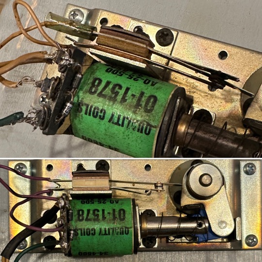
Here’s how a flipper works.
That big electromagnet is actually two coils in one: a high-power coil to drive the flipper up with great force, and a low-power coil to hold the flipper up at the end of the stroke. 
The flipper reaches the end of stroke (EOS), and opens a switch to disconnect the high-power coil, leaving the low-power coil to hold the flipper up while you hold the button. This way the coil doesn’t burn up while you plan your next move.
(Modern games also have EOS switches but they’re wired differently. More on that another time.)
Taxi’s flipper started jackhammering. It was caused by a broken low-power coil lug. The high-power coil fires, the EOS switch opens, the high power coil is disconnected but there’s no low-power coil to hold the flipper up…so it starts to fall back down. The high-power coil re-fires, and we have a jackhammer.
Added some wire to improvise a new lug, resoldered everything and we’re back in action 🤙😊
2 notes
·
View notes
Text
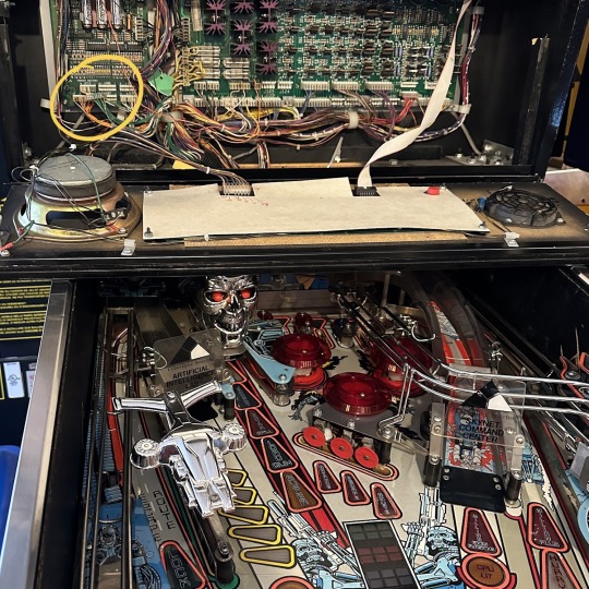
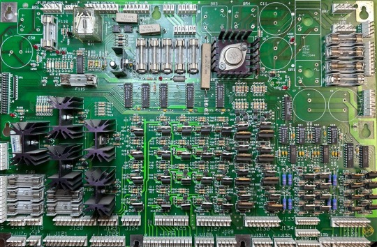
Terminator 2 has been off the floor for a little while. It’s the second one I’ve owned over the years, and if I were to sell it I would miss the super jackpot music but I’d probably not buy a third. Anyway there’s a few things that need doing. The gun trigger spring broke so it was all floppy. That’s fixed. Next the GI is wrong, partly because of a botched re-pin from a prior owner. But before digging into that I noticed some green gunk in the backbox under the batteries. My batteries are leakproof lithium so that would have been something I didn’t notice when I first got it.
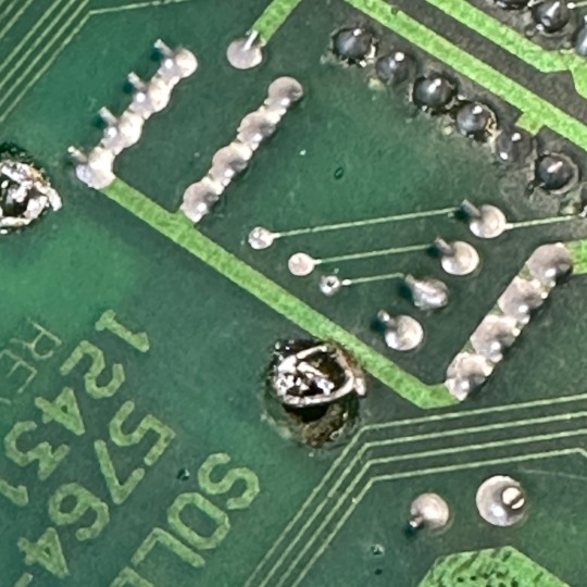
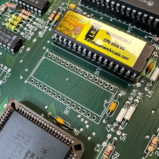
So I took a fresh look at the MPU board. Turns out there’s a fair bit of prior repair. This game has been through some things. Look at all the sockets—somebody replaced all those chips for some reason. Plus the terminal under that battery looks suspicious.
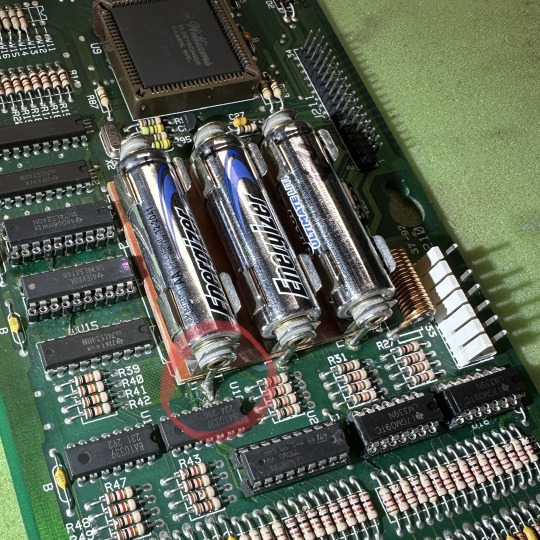
Prior owner also removed the battery holder, damaged the board in the process, did a clever hack involving a small circular wire to replace the pad they yanked off, and *reinstalled the battery holder instead of relocating it.*
Next: remove the RAM and replace with NVRAM. No more batteries! I’m getting better at clean chip removal.
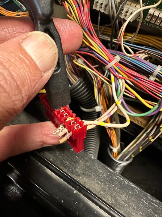
Next—get a load of this GI repin 🙈 Wrong size replacement connector, re-used old burned connector broken into two bits, improper tool used to fasten the wire, which isn’t trimmed even close to right. Ick!
The game’s test mode can be used to verify which color wires belong on which pins. Press “start” during a specific coil or GI test and it scans through all kinds of extra information. Use a proper IDC punch tool and figure out which direction everything should point. Once you’re sure, it takes a bunch of force to get those wires properly seated.
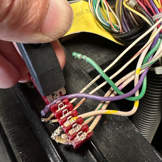
So that’s much better. The CPU string still doesn’t work. I suspect a problem on the PDB. Saving that for next time!
0 notes
Text
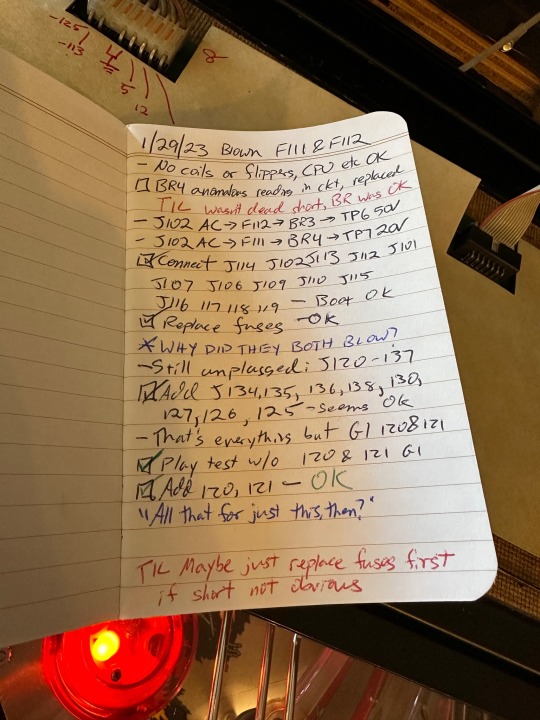
TIL if a fuse blows and there’s no obvious short maybe just replace the fuses and see what happens instead of going into ratholes
0 notes
Text
Asteroids enters a new era
There’s a long thread on the bird app detailing my Asteroids repair saga. It’s been a long journey and I’ve learned a ton since first putting my hands on this machine.
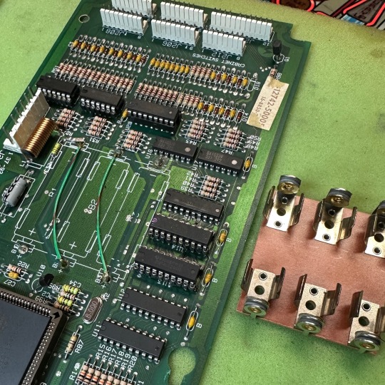
Fixed busted fuse assembly
Played it a little
Had issues where it wouldn’t boot
Decided the cause was a bad edge connector, without using science
Soldered in a new connector, badly
Did it again, properly
Replaced all the electrolytic capacitors for no good reason
Recapped the monitor too, and its HV section, for no good reason, replaced two resistors with jumpers because the internet says so
Of course it didn’t work
Let it languish for a year, nearly sold it
Shorted/smoked something poking randomly at it with my new oscilloscope for no good reason
Let it languish awhile longer
Got a clue somehow
Replaced the blown voltage regulator in the video section
Replaced a blown fuse in the monitor
Figured out how to the the game to display its picture on an oscilloscope!
Analyzed the monitor harness, concluded the voltages were right
Found the brightness/contrast pots on the monitor 🫢
It works, except enemy ships don’t make a “pew” fire sound, it’s always been like that
Traced the problem using Atari’s exceptional contemporaneous schematic to what seemed like a faulty 555 chip
Replaced it
OMG it works
Mitigated some RF interference issues using science and some ferrite beads
Come play it!
0 notes
Text
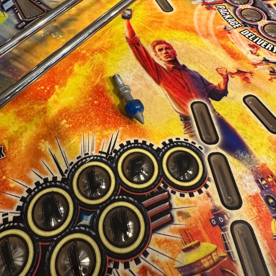
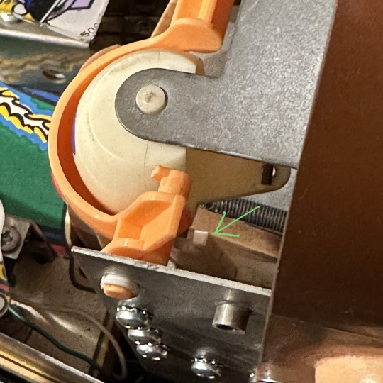
Dialed In needed some routine maintenance, precipitated by a customer pointing out this loose piece 😳
Couldn’t see where it went right away so I started cleaning and found some more issues. Like this janky flipper.

I like the easy ones. Broken spring. Easily replaced.
The lower left flipper was starting to come loose. Never saw a crank do that before.
Tightened it right up and noticed a bunch of iron filings. Won’t be long before it’s time to rebuild the flippers.
Then finally I figured out where that post belongs. Oh yes, the infernally difficult SIM card slot!
1 note
·
View note
Text
I once lived in a house where everywhere I looked, there was evidence that someone had performed “maintenance” in an odd way. Like a toilet paper holder nailed into drywall with 30 randomly placed finishing nails.
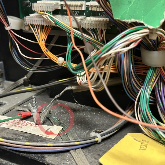
Terminator 2 started intermittently acting up a few days ago—wouldn’t start a game because a pinball was missing. This machine has four switches (15, 16, 17 and 18) to manage the balls as they inevitably drain into the outhole. All four were intermittently failing to register. When one failed, they all failed. But they weren’t failing consistently.
It does sometimes happen that a microswitch like this can fail—happened on both of Twilight Zone’s coin switches. But they don’t all four fail intermittently at once.
Fixing pinball machines is like solving a puzzle. What do these failed switches have in common?
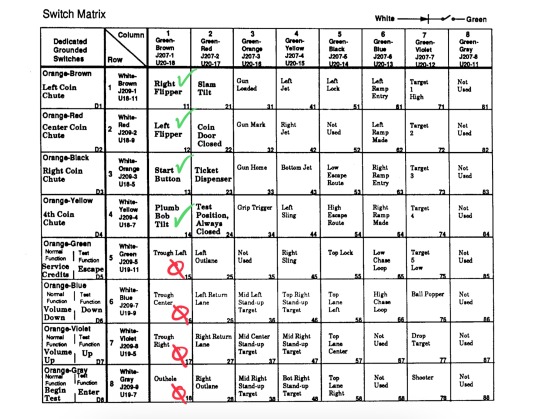
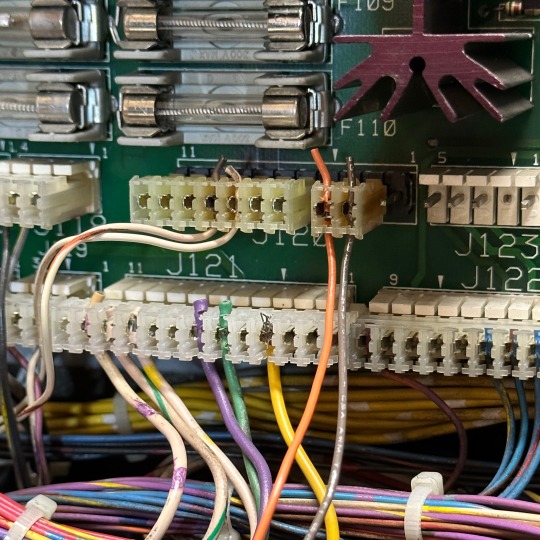
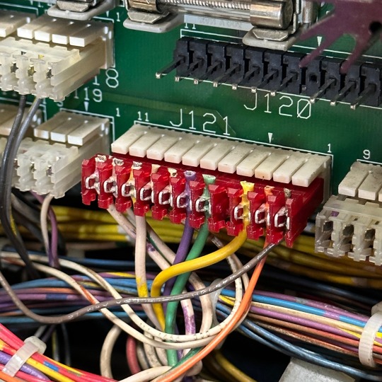
They’re all on the green/brown column. Key clue—all of the playfield switches on green/brown are having trouble. The other four are working fine, and they’re cabinet switches with separate wiring and a different connector. This tells us where to look!
Here’s what made me think of my old house. The connector in question is the wrong size. Somebody replaced it and didn’t have the right one handy. Also they did a poor job seating the wires in the connector so one was intermittently loose. Actually two! (If that green/yellow wire comes loose, which switches will be impacted?)
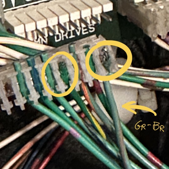
Arcade operators aren’t proud. The game doesn’t have to be perfect, it just has to keep earning. I don’t have the right connector handy either, nor do I want to spend two hours building a perfect connector to replace this hacked-up one. So I cut off the frayed bit of both of those outlier wires and used a vice-grip plier to jam them into their seated position. This may come back to bite me someday. when it does, perhaps that will be my opportunity to fix the fact that the “CPU” lights at the center of the playfield don’t work. That’ll be another story.
0 notes
Text
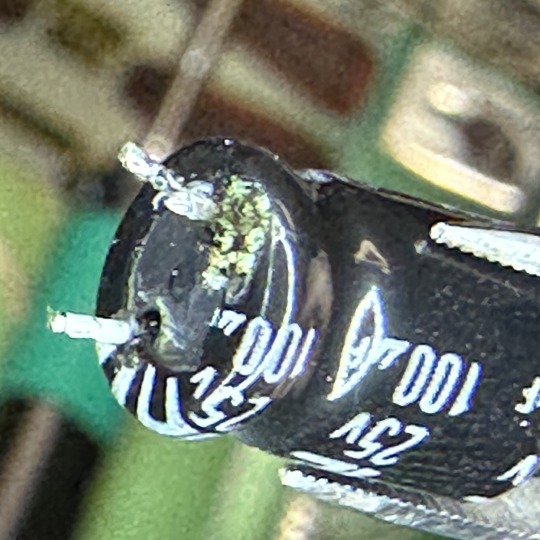
Last week I addressed some corrosion by the battery on the MPU in my customer’s Addams Family. Now we have C2 from the PDB causing even more trouble.
The symptom: “check F114 and F115” message on the screen came up after installing the repaired MPU board. That’s because there’s a permanently closed switch by the coin door that the computer uses to make sure the 12V switch matrix is working correctly. If it can’t detect the closed switch, it throws this error. There’s no regulated 12V in this game, not because a fuse is bad, but because electrolytic capacitor C2 leaked causing the 12V circuit to deliver less than 1V. (Q2, to the right of C2, is responsible for regulating a clean 12V. You can’t see it in this photo but its terminals are gunked up too.)
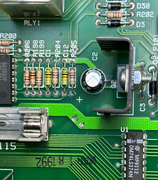
Look at all that green goop. A bunch of resistors and those two little caps to C2’s left need removed so I can clean that area. This creeping corrosion will destroy the whole board if you let it. You can’t tell C2 is bad just by looking at it but a close look at the underside gives it away.
Cleaned and replaced those components. Installed new C2 and new Q2. Don’t know if Q2 was blown but no reason to save the old one.
And while I’m here let’s replace the other caps that go bad, and all the bridge rectifiers. Here’s the board with a bunch of the bigger components removed while I wait for the kit from Marco.
1 note
·
View note
Text
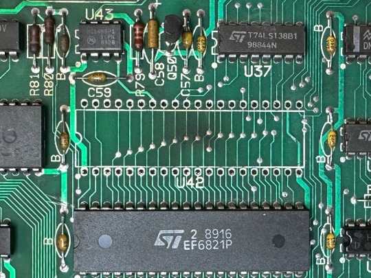
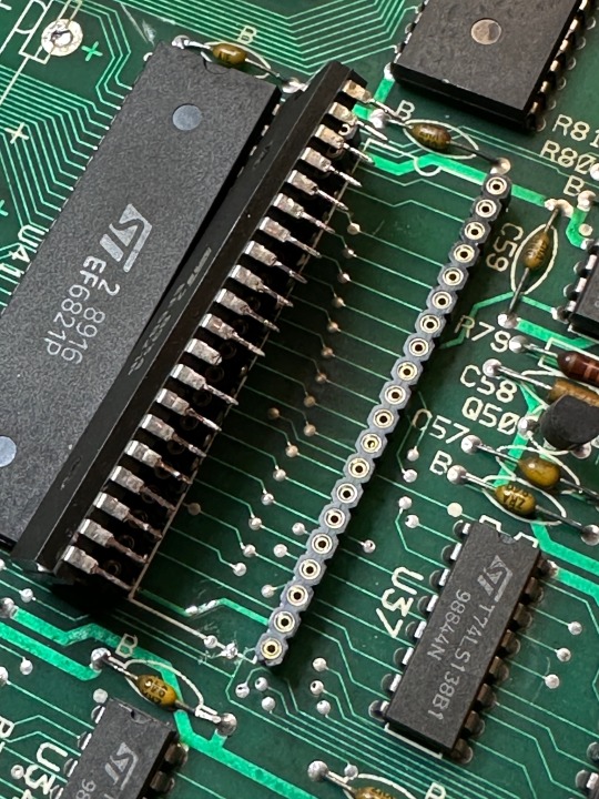
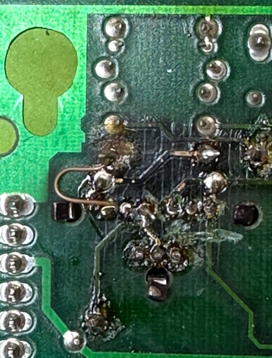
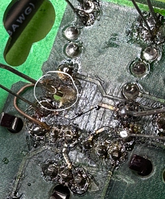
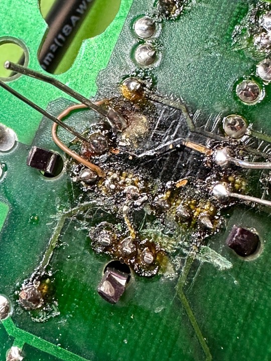
While awaiting the arrival of the PIA chip that I hope will be the answer to the Space Station saga, I went ahead and desoldered the (hopefully) bad one. It’s a good practice to add a socket in case the chip needs replacing again some other time. And it’s also a good practice to have a chip in the socket as you solder it in, to make it easier to align everything. Except that a pin from the bad PIA broke off in the new socket. Using the sharpest razor blade I could find I was able to pry the little bugger out.
Also the burned discoloration behind the chip gives me further hope that I’m replacing a failed component.
0 notes
Text
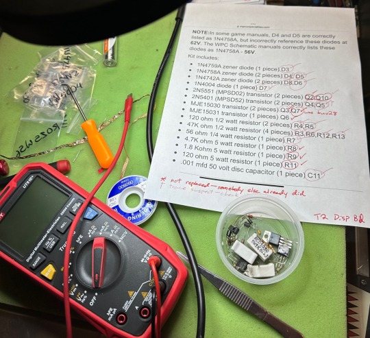
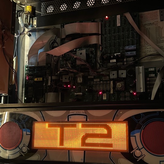
T2 original display saved; nature of existence pondered
Terminator 2’s display was suddenly faded last week. This happens when components in the high voltage section of the display board reach the end of their life. Many of our games from this “WPC” era have newfangled color displays, which only need 12V—their HV circuits can fail and it doesn’t matter. I kept this original monochrome display in T2 partly because it’s interesting, and mainly because the animations in this game are (IMHO) too primitive to warrant colorization.
The board has been worked on before. It’s kind of a goopy mess, and one trace was repaired by the last person; we’ll preserve that repair instead of replacing it.
Here’s a look at a thru-hole for D3 that’s just…gone. That was a bad burn that led to this earlier repair. And then a picture of the same hole with the original trace-repair wire soldered to the new D3.
Here are the components that were replaced. Marco sells a great kit just for this situation.
Kind of like cells in your body, come to think of it. We can replace these bits and the game is still T2, right? Is it the same T2? Are you the same you? 🤔
Anyways it works again. Here’s the after pics.
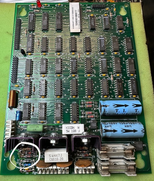

Don’t forget to discharge those two HV caps on the board before you do, well, anything—they retain 100V of charge for a good long time after the board is removed from the game. Ask me how I know.
0 notes
Text
Mata Hari cleaned & waxed, left flipper rebuilt
Here’s a photo (before cleaning) for reference to monitor playfield wear. I also rebuilt the left flipper. New plunger link, same coil stop, same coil sleeve. New EOS, new solder, nice clean wiring.
1 note
·
View note
Text
Space Station — an epic saga
This feels as deep as I’ve ever had to go. Bride of Pinbot helmet repair was pretty deep, and so was the Whirlwind corrosion repair, but there are/were no less than seven different things wrong with our Space Station. Let’s get into it.
It wasn’t leveled correctly. It was too steep, making the ramp shot too hard and making the play just…wrong. Easily fixed. Half a degree is all it needed.

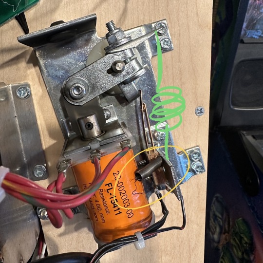
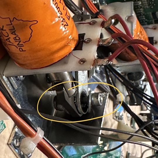
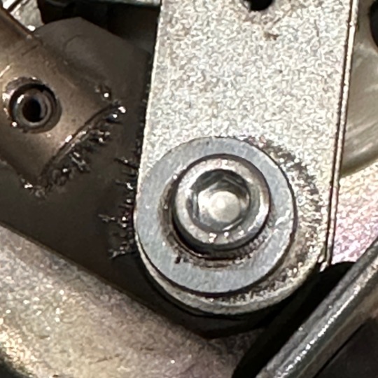
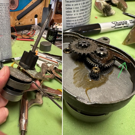
Space Station Gearbox Dogbone Failed. The space station diverter gadget is only supposed to turn counterclockwise. The motor receives alternating current, so it’ll start randomly in a CW or CCW direction. The gearbox has a little “dogbone” thingy that impedes travel in one direction, causing the motor to jam and change direction. The gear that interfaces with the dogbone wore out. I bent the dogbone tooth slightly rather than ordering a new motor, which I’ll have to do when this hack fails.
There’s a few lamps that aren’t working or are the wrong color. Easily addressed.
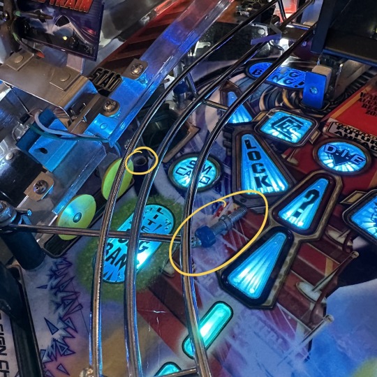
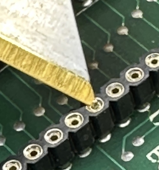
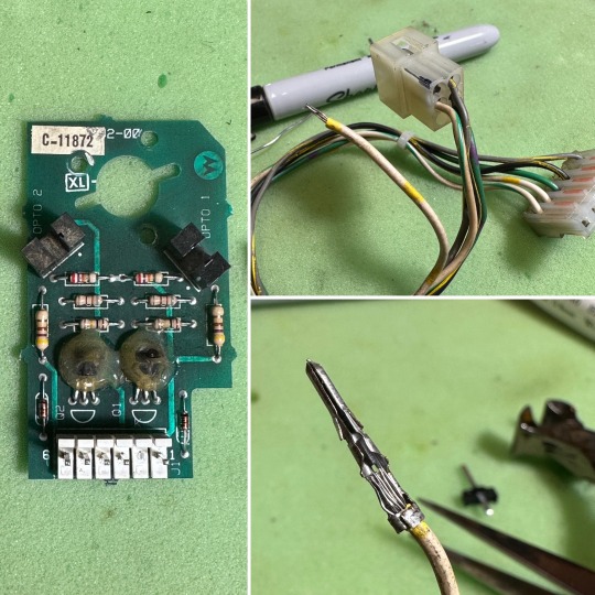
So many broken wires. Well a couple. In particular the station optos weren’t working right. There are two optos on a board that the game uses to determine the orientation of the rotating space station diverter. One wasn’t working. I pulled the board and replaced what I thought was the failed opto. What I learned: make fewer assumptions. All it really was is a broken wire in a harness. Bottom right is before I applied solder to the original pin because I don’t have spare pins for this kind of connector.
Left Popper Run Amok. This one was the one that was most annoying to players. The symptom was that a locked ball would randomly pop into play for no reason. Multiball is fun, but glitch multiball is just confusing and bad. This went on for months and months before I finally noticed the cause: the left ball popper solenoid (#3a) was firing not just when its switch was closed, but simultaneously with ten other solenoids. Whenever the game fired the outhole kicker, the shooter lane feeder, the pop bumpers, and a bunch of others, the left popper would also fire.
By itself this wouldn’t necessarily be an issue, except that when the left ball popper fired, it would sometimes (but not always) cause its own switch to close. The effect of this was that any time any of those other coils would fire, the game would sometimes (but not always) think that there was a ball locked in the left popper, ready to be fired up and away. If a ball was already locked, then that ball would be ejected to make room for the ghost ball that wasn’t there in the first place. Oof.
So why was Solenoid 3A firing along with 1A, 2A, 4A, 6A, 7A, 8A, 17, 19, 21 and 22? In the end I’m sure I don’t know. I spent a ton of time poking at the aux driver board, learning where all the wires on all those connectors go. And I connected my oscilloscope to some stuff. The closest I got to a full understanding is that those coils are powered by circuits which—like 3A—are actuated by transistors on the aux board, not on the main driver board.
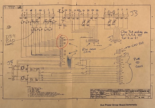
Very late in this process, having printed a ton of schematics and randomly tried a bunch of stuff, I noticed that D34 on the aux board is blown. The semiconductor is now just…a conductor. That’s definitely not good, but how precisely that would cause this symptom eludes me. Anyway it’s a CR3-010, aka MR501, aka 1N5401, which I have ordered.
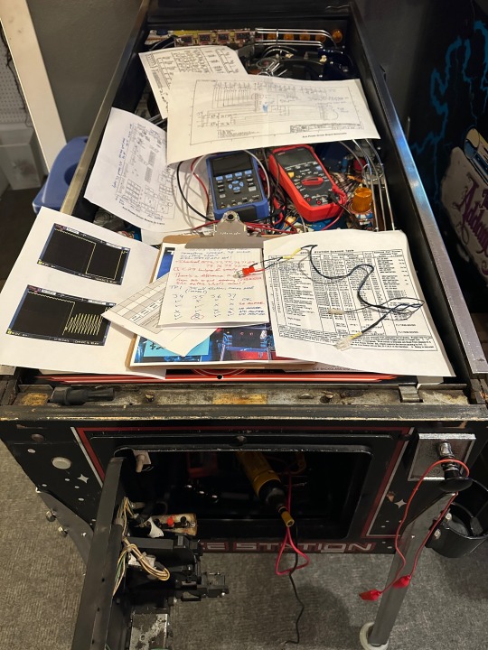
But I also blew up the MPU board. Because I’m still learning to apply science (which is about making hypotheses, then devising tests to confirm those hypotheses, then carefully and deliberately executing those tests) as opposed to just randomly trying stuff to see what happens, I caused the game to pop and go silent when I connected a particular wire to a particular connector. Turning it on again produced this—
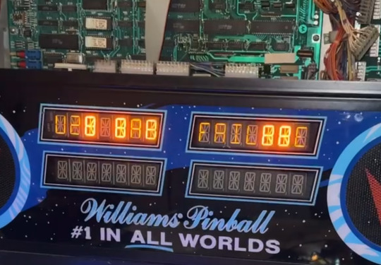
That message is a little hard to read, but the LEDs on the MPU are clear. Ten blinks of the “blanking” LED and one blink of the “diagnostics” LED. That indicates RAM failure.
I checked D1 and it seemed wide open so I replaced it. What I learned is that the game should be off with the batteries removed for that test to be valid. I replaced a perfectly good diode.
So after confirming that the RAM chip was receiving power on pin 32 from the batteries as well as the mains, and after checking D2, I took the error message at its word and set about replacing the RAM chip.
But I don’t have a CXK5816PN-12L on hand. What I have is some AnyPinDMD+ NVRAM chips, which are super-cool and a really nice way to keep old batteries from ruining pinball machines. After checking to be sure that a 5816 chip is compatible with a 6116 chip, I had to reconfigure the NVRAM PCB by moving a bubble of solder from the “6264” to the “6116” pads, and by installing a pair of 10K resistors on the underside. This was my first effort at any kind of SMD soldering, and thanks to my amazing new Pine64 soldering iron it was a breeze.
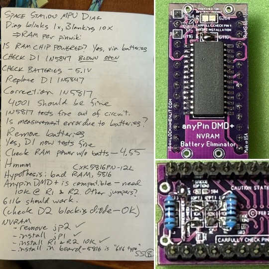
I desoldered and removed the old RAM. I installed a socket and plugged the NVRAM into the socket. I reconnected the board’s power connector to a harness I had made and attached to a standard PC power supply, which is a handy way to test a pinball board outside of the game. To my delighted astonishment the three test LEDs started blinking in a healthy way, which gives me confidence that the MPU is happy again.
I guess that’s all for now. To do—
Wait for parts
Install new diode in Aux board
Check for misfire
Clean up lamps
Playyyyyyy it!
0 notes
Text
Rudy’s lazy eye…again

Poor grumpy Rudy. His eyelid broke loose. Last time it was the $50 eyelid itself that was broken. This time it’s the link that actuates the lid.
New link ordered.
4 notes
·
View notes
Text
There’s been a breakthrough on Road Show.
Look how effortlessly those jaws are moving! Red and Ted have been sluggish and slack-jawed for months and months and months. But after all these years owning pinballs, I’m finally–finally!–starting to take a more deliberate and scientific approach to fixing chronic issues.
Knowing what I know now, here’s how I’d approach this problem next time.
Is it a mechanical problem?
No. The motors move smoothly. They were recently replaced and the gears freshly lubed because the last guy (me) didn’t try to use science to fix the problem.
What’s the voltage at the motor?
Oh. Well there’s the problem. These motors are receiving only ±2.5V during the test sequence. Rudy’s jaw on Funhouse is working well and his motor is receiving a little over 5V.
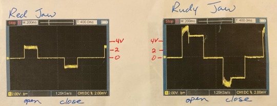
What’s the voltage at the motor driver board inputs?
10-11V. Rudy’s driver board input varies from 12 to 15V.
Where’s that saggy voltage coming from?
BR5. There’s about a volt of sawtooth ripple on the upper left leg of that rectifier, which is only supplying 11.6 V.
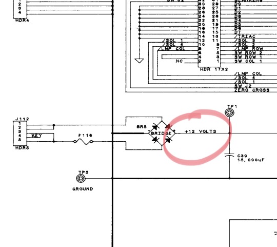
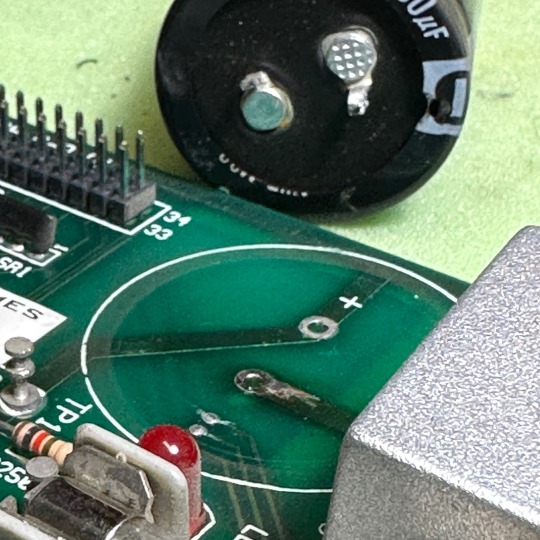
So? Replace BR5 and C30.
Done. And guess who got that capacitor out without ruining the thru-holes, for the first time? This guy!
So did it work?
Yes :-)
0 notes
Text
Hi pinball people! Will From Nehalem here, associate repair intern at North Coast Pinball. I’m pretty sure it’s time to transition from the bird app to here because…well, because of reasons. Our promo stuff will still mainly be at Instagram and on Facebook. Here we’ll be posting about the nerdy stuff, which mainly amounts to pinball repair and maintenance. Ask anything!
2 notes
·
View notes